Generator field endwinding blocking

a technology of endwinding coils and generators, which is applied in the direction of magnetic circuit rotating parts, dynamo-electric machines, magnetic circuit shape/form/construction, etc., can solve the problem of increasing the tear load to pull the cap ou

Active Publication Date: 2022-10-27
GENERAL ELECTRIC CO
View PDF0 Cites 0 Cited by
  • Summary
  • Abstract
  • Description
  • Claims
  • Application Information

AI Technical Summary

Benefits of technology

[0006]A fastener, such as, for example, a pin, is placed in the at least one transverse hole of the blocking and the at least one hole in the portion of the cap in the slot, securing the cap with the blocking. To this extent, there is a vertical engagement between the blocking and the cap, and a horizontal engagement block between the cap and the endwindings. This vertical engagement and horizontal engagement lock the blocking, the cap, and the fastener together. As a result, the contact area of the cap to retention can be significantly increased, thus increasing the tear load to pull the cap out. Further, affixing the cap within the slot, as opposed to the top surface of the blocking, makes the design of the various embodiments less prone to becoming easily damaged during assembly.
[0007]The various embodiments have several benefits over the existing retention mechanisms such as those that use rivets to hold in place the blocking deployed in a generator rotor. First, the retention mechanism of the various embodiments is much more durable against hammer blows or any impact on the top of the blocking which can happen during installation. Second, the retention mechanism of the various embodiments has a higher shear / tear strength from lateral loads seen in service of the generator rotor. Third, the assembly of the retention mechanism of the various embodiments can be made of entirely non-metallic components which is beneficial as any loose metallic components can cause electrical shorting in a generator field winding. As a result of these benefits, the solution offered by the various embodiments is cost effective and robust to assembly and operational loading.

Problems solved by technology

As a result, the contact area of the cap to retention can be significantly increased, thus increasing the tear load to pull the cap out.

Method used


Image

  • Generator field endwinding blocking
  • Generator field endwinding blocking
  • Generator field endwinding blocking

Examples


example 1

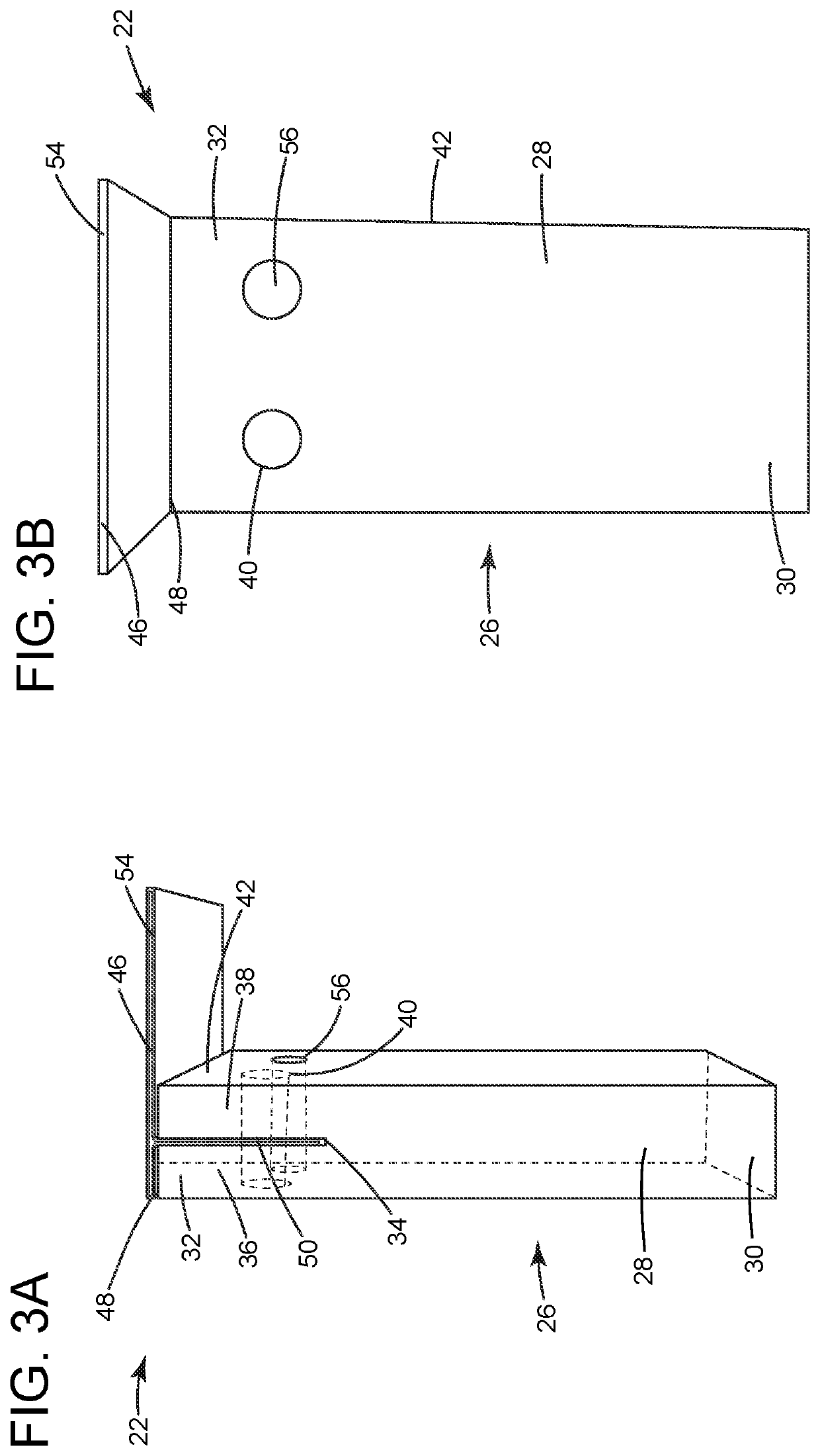
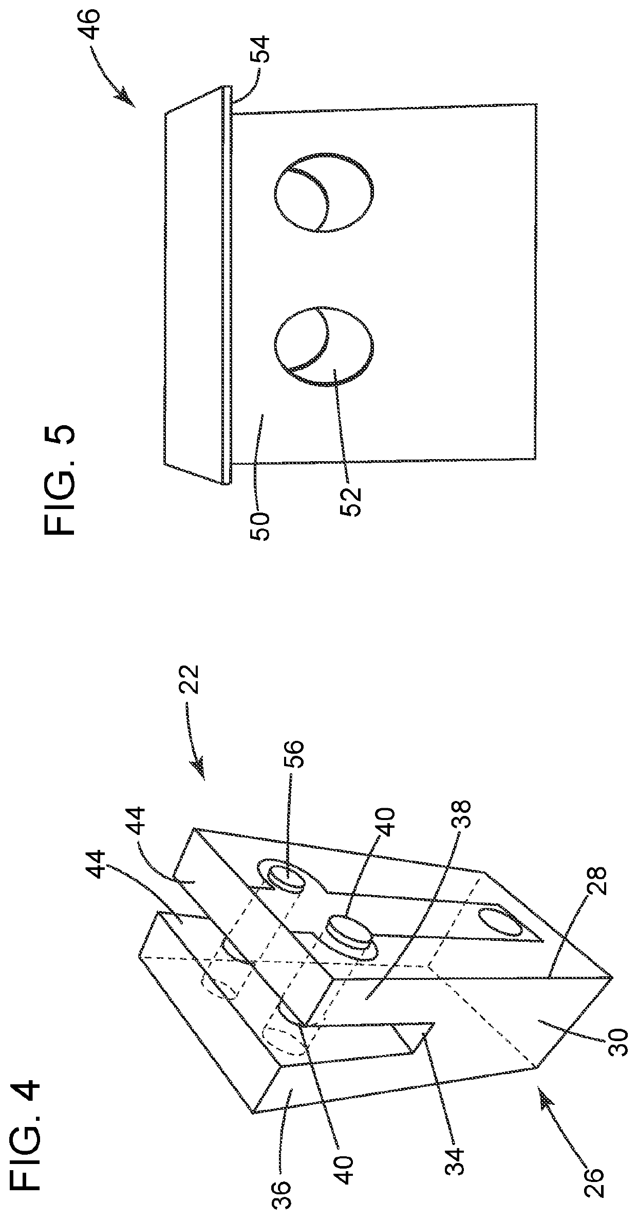
[0042]In this example, an endwinding blocking member with a “dual” cap configuration was produced. In this example, two caps formed of NOMEX were inserted into a slot machined in a glass-based blocking. Each of the caps included a long bended section extending out from the slot and along a top surface of the blocking in opposing directions and extending beyond the periphery of the top surface. The portion of the caps in the slots each had two holes aligned with two transverse holes in the blocking. Pins were inserted into each of the holes in the blocking and the corresponding aligned holes in the caps, locking the caps to the blocking. After formation, the endwinding blocking member with the “dual” cap configuration underwent a series of tests to demonstrate the holding power of the “dual” cap. These tests included pull tests in vertical loading to simulate assembly, hammer tests to establish ability to withstand vertical hammer blows, hammer and vertical pull tests establishing th...

example 2

[0043]In this example, a bonding material was applied to an endwinding blocking member with an “L” shaped cap as described herein. In this example, the bonding material was applied to the “L” shaped cap, and between the “L” shaped cap and the blocking member. In this example, the bonding material that was applied included an epoxy filling compound (A50A233). The endwinding blocking member with the “L” shaped cap was subjected to the same testing described in Example 1. The tests showed that the “L” shaped cap with the epoxy filling compound on the cap experienced peak separation force at 85 lbf, while the configuration with the epoxy filling compound on the cap and the block showed separation starting at ˜20 lbf, full separation at ˜75 lbf, and peak separation force at ˜185 lbf.

example 3

[0044]In this example, the epoxy filling compound was applied to an endwinding blocking member with a “T” shaped cap as described herein. In this example, the epoxy filling compound was applied to the “T” shaped cap, and between the “T” shaped cap and the blocking member. The endwinding blocking member with the “T” shaped cap was subjected to the same testing described in Example 1. The tests showed that the “T” shaped cap with the epoxy filling compound on the cap started experiencing separation at ˜10 lbf with peak separation force occurring at 70 lbf, while the configuration with the epoxy filling compound on the cap and the block showed separation starting at ˜20 lbf, full separation at ˜60 lbf, and peak separation force at ˜115 lbf.


PUM


Abstract

Generator field endwinding blocking is described. The endwinding blocking has a spacer block for radial placement between rotor endwindings. The spacer block has a spacer body with a radially inboard end, a radially outboard end, a slot extending from the outboard end towards the inboard end, and at least one transverse hole formed on an outer surface of the spacer body, extending in a perpendicular direction towards the slot. A cap covers at least a portion of the outboard end. The cap has a radially inward portion received in the slot with at least one hole aligned with the at least one traverse hole, and at least one end extending beyond a periphery of the outboard end towards an adjacent endwinding. A fastener placed in the holes of the spacer block and the radially inward portion of the cap, secures the cap with the spacer block.

Description

BACKGROUNDTechnical Field[0001]Embodiments of this disclosure relate generally to generator rotors and, more specifically, to the blocking of endwinding coils of field windings of generator rotors.Discussion of Art[0002]The endwinding coils of the field windings of a dynamoelectric machine, such as, for example, a generator rotor, are typically spaced with insulating blocking. This blocking retains the integrity of the coil stacks, transfers lateral and circumferential thermal expansion loads, and provides space for ventilation, among other features. Correct alignment and position of the blocking is necessary for proper functioning of the generator field windings. During both assembly and service of the generator rotor, the blocking can experience significant loading (e.g., force due to assembly of all components, crushing from retaining ring assembly, turning gear cyclic gravity loading, centrifugal loading at 3000-6000 g, thermal expansion loading, etc.). The retention mechanism t...

Claims


Application Information

Patent Timeline
Patent Type & Authority Applications(United States)
IPC IPC(8): H02K3/51
CPCH02K3/51H02K5/04H02K5/02H02K5/24H02K1/26H02K3/28H02K3/34H02K3/48
Inventor DRAINA, KEVIN MITCHELLRIGOSU, ANTHONY
Owner GENERAL ELECTRIC CO
Why Eureka
Try Eureka