Screen mapping of a cathode ray tube

a cathode ray tube and screen mapping technology, applied in the field of cathode ray tubes, can solve the problems of inability to achieve consistent, objective and repeatable adjustments with a manual system, inconvenient hiring and retention of employees, and inaccurate measurements

Inactive Publication Date: 2000-01-11
DISPLAY LAB
View PDF28 Cites 29 Cited by
  • Summary
  • Abstract
  • Description
  • Claims
  • Application Information

AI Technical Summary

Problems solved by technology

Operator fatigue often results in inaccurate measurements.
Additionally, consistent, objective and repeatable adjustments are not obtainable with a manual system.
It is also difficult to hire and retain employees who are willing to work late hours to increase factory throughput.
Although these transformation equations provide adequate correction for distortions that occur over most portions of the screen, the distortions that occur on some portions of the screen, particularly along the outer edges and the corners, are too severe to be accurately corrected using these standard correction voltage waveforms.
Use of vision systems by both monitor manufacturers and cathode ray tube manufacturers results in a duplication of effort and unnecessary capital expenditures.
These cathode ray tube specifications (exit criteria) are often difficult to meet and require skilled technicians to achieve these results.
This may limit the production throughput and yield of the cathode ray tube manufacturing plant.
Additionally, the techniques of manually aligning the deflection and control circuitry and electron guns on a tube is time consuming and tedious work that is subject to

Method used


Image

  • Screen mapping of a cathode ray tube
  • Screen mapping of a cathode ray tube
  • Screen mapping of a cathode ray tube

Examples


Embodiment Construction

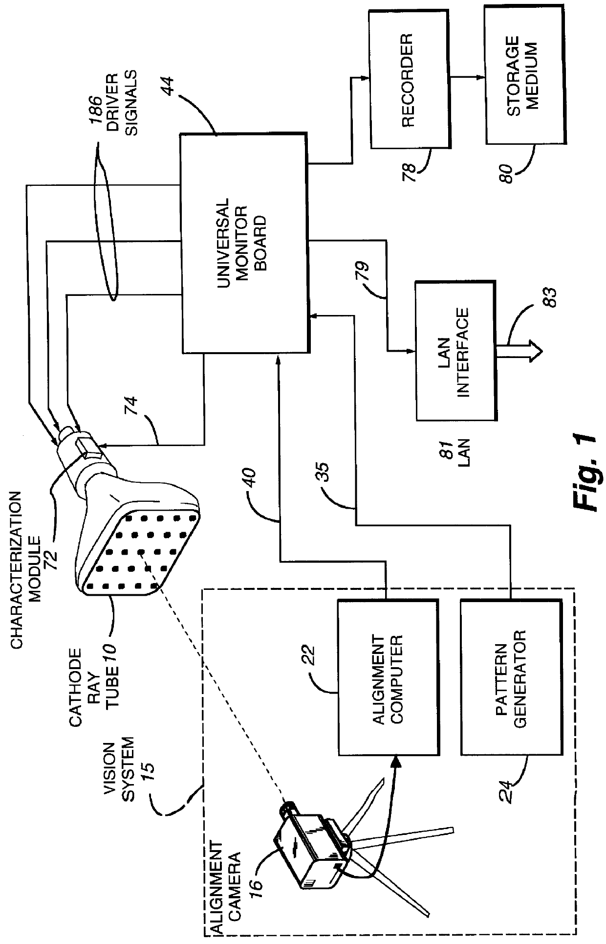
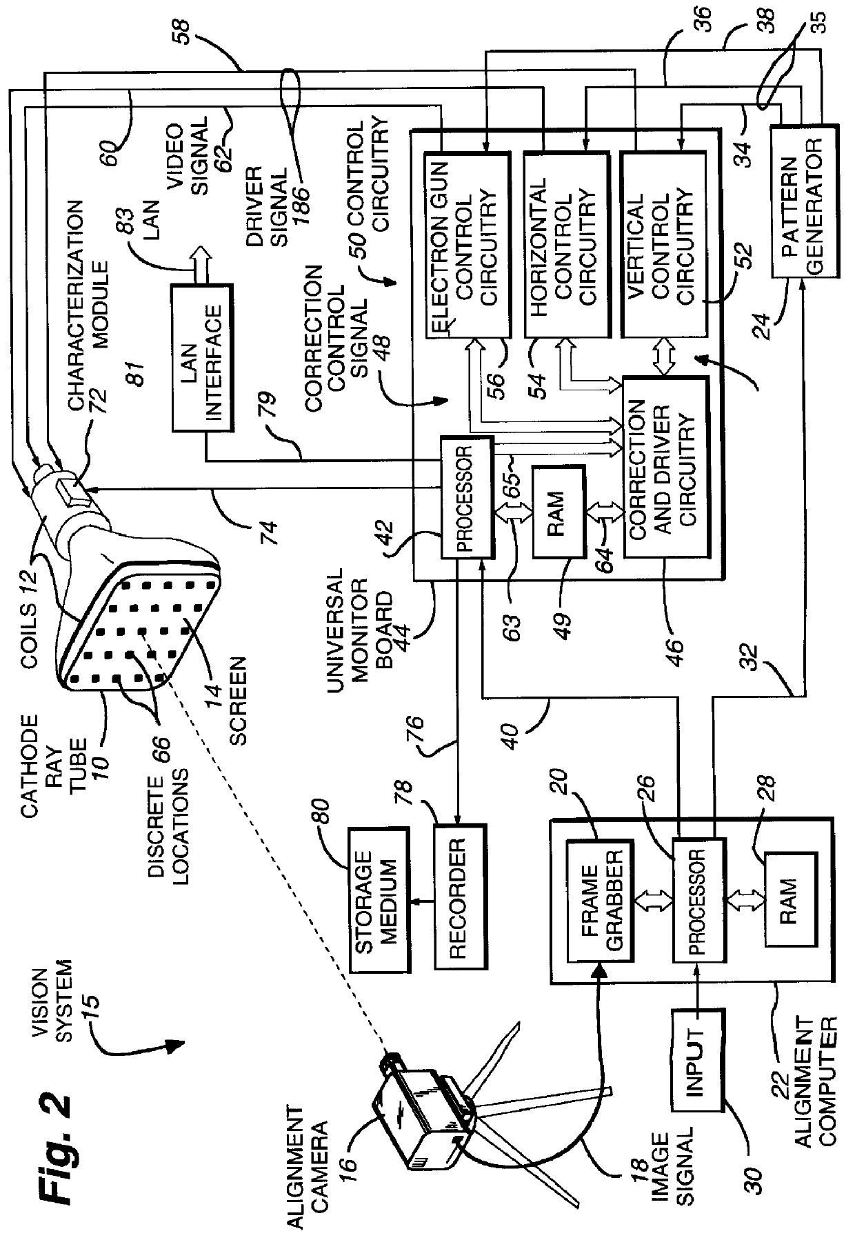
FIG. 1 discloses a schematic illustration of a system for generating maximum correctable distortion data, correction factor data, and parametric data. Hence, cathode ray tube 10 can comprise a golden tube when maximum correctable distortion data is being generated, and a production cathode ray tube when correction factor data and parametric data is being generated. A vision system 15 is positioned such that alignment camera 16 records a video image of a pattern displayed on cathode ray tube 10. The alignment computer 22 captures the video image and analyses it to produce either correction factor data, parametric data or maximum correctable distortion data that is transmitted to universal monitor board 44 via connector 40. When the system of FIG. 1 is being used to map the screen of cathode ray tube 10 to provide alignment data, either correction factor data or parametric data are generated by alignment computer 22 depending upon the particular type of monitor board that is going to ...


PUM


Abstract

A system for generating correction factor data that is representative of the distortion characteristics of a cathode ray tube. The correction factor data is stored with a cathode ray tube to allow later alignment of a video signal, or can be provided on a storage medium or on a network. Distortion data, and resultant correction factor data is generated for a series of discrete physical locations on the cathode ray tube screen. In this manner, the entire screen surface can be utilized to align a video image. Maximum correctable distortion data is also generated in accordance with the present invention to provide exit criteria for cathode ray tube manufacturers. The exit criteria is based upon maximum correction factor data that can be generated to correct distortions. A characterization module is provided that can be coupled to cathode ray tube coils that stores the correction factor data or an identification number for the cathode ray tube that can be used to retrieve the correction factor data from any desired source such as CD ROMS, a LAN, a database coupled to a WAN, or the Internet, etc. Interpolation techniques can be used to generate correction factor data for any desired number of interpolation points based upon correction factor data provided for a lesser number of characterization locations.

Description

FIELD OF INVENTIONThe present invention pertains generally to cathode ray tubes and more particularly to the alignment of video signals on cathode ray tubes.DEFINITIONSAlign means to cause a video image to be adjusted to that distortion characteristics are minimized and the video image that is displayed on the cathode ray tube forms an image that is pleasing to the eye.Alignment camera means the video used to generate a signal that is representative of the image displayed on the cathode ray tube in a manner described in U.S. Pat. No. 5,216,504.Alignment specifications means a limit set for the distortion data of each correction factor parameter to provide an aligned video image.Bar code means any sort of optically encoded data.Cathode ray tube means the tube structure, the phosphor screen, the neck of the tube, the deflection and control windings, including the yoke and other coils, and the electron guns.Characterization module means a device that is coupled in some manner to a cath...

Claims


Application Information

Patent Timeline
IPC IPC(8): H01J9/44H04N17/04
CPCH01J9/44H04N17/04
Inventor WEBB, JAMES R.SIMPSON, RON C.
Owner DISPLAY LAB
Why Eureka
Try Eureka