Slotted pacing/shocking electrode

a pacing/shocking electrode and electrode technology, applied in the field of lead, can solve the problems of reducing the diameter of the electrode, tricky path, and traditional ring electrodes tend to be relatively long and inflexibl

Inactive Publication Date: 2000-01-25
CARDIAC PACEMAKERS INC
View PDF10 Cites 143 Cited by
  • Summary
  • Abstract
  • Description
  • Claims
  • Application Information

AI Technical Summary

Problems solved by technology

This is a tricky path which is best navigated by first using a guidewire and then sliding the lead over the guidewire.
Traditional ring electrodes tend to be relatively long and inflexable.
However, as the diameter is reduced strength can be lost.
The joints cause potential weak spots in the lead.

Method used


Image

  • Slotted pacing/shocking electrode
  • Slotted pacing/shocking electrode
  • Slotted pacing/shocking electrode

Examples


second embodiment

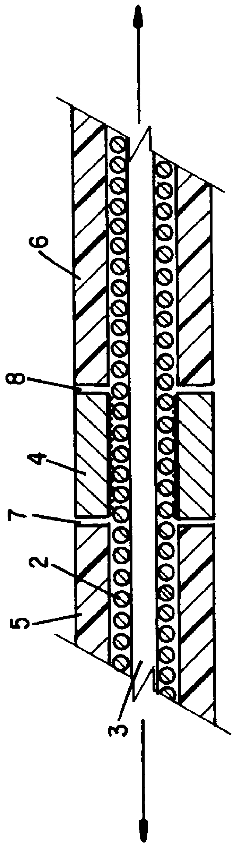
FIG. 5 is a cross-sectional view of a In this embodiment, the conductor member 12 is surrounded by an insulative covering 20. The insulative covering 20 can be made of silicone rubber or any other suitable material. In this embodiment, the ring electrode 14 has a cylindrical outer surface 17. However, the inner wall 16 is not cylindrically shaped. Instead, one or more teeth 24 are provided. The teeth 24 extend toward the conductor member 12 and are used to weld the conductor member 12 to the ring electrode 14. The teeth are separated by slots 19. These slots 19 extend the length of the ring electrode 14 and are filled to form a bridge 23 integrally formed with and made of the same material as the covering 20. In this embodiment, the bridges 23 cooperate with the teeth 24 and with the remainder of the covering 20 to improve the axial strength of the joints between the covering 20 and ring electrode 14.

third embodiment

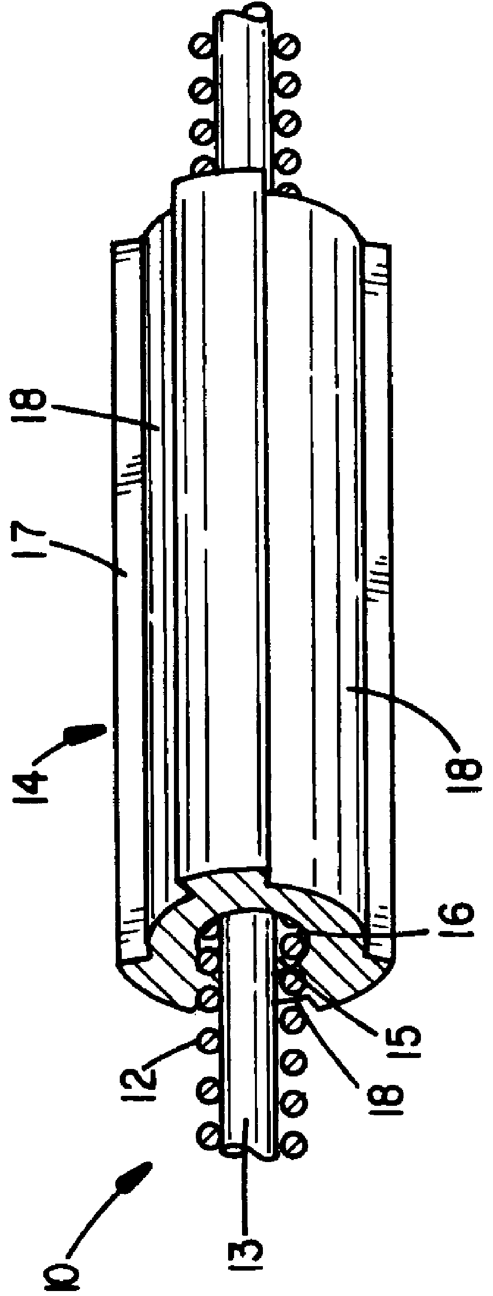
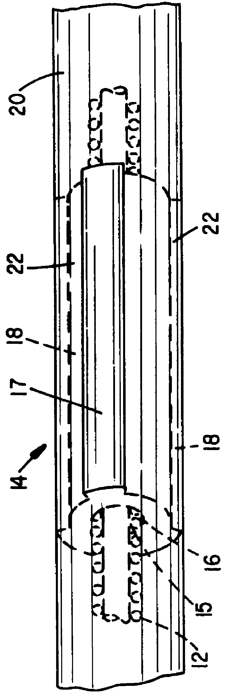
FIG. 6 shows a This embodiment again includes a conductive member 12, an insulative covering 20 and a ring electrode 14. In this embodiment, however, neither the wall 16 nor the inner surface 17 are cylindrical. Instead, the wall 16 includes teeth 34 separated by slots 19. The outer surface 17 also includes slots 18 extending into the areas of the ring electrode 14 incorporating the inwardly projecting teeth 34. Thus, when the insulative covering 20 is formed, inner bridges 23 are formed in the slots 19 between the teeth 34 and outer bridges 22 are formed in the slots 18 which extend into the teeth 34. Since the slots 18 and 19 extend the entire length of the ring electrode 14, the bridges 22 and 23 are integrally formed with the portions of the covering 20 proximal and distal to the ring electrode 14.

Electrodes incorporating the features of the present invention have significant advantages over prior art electrodes. First, electrodes made in conformance with the present invention ...


PUM


Abstract

A lead for use in conjunction with a cardiac rhythm management device includes an electrode coupled to a conductor. The lead includes an insulative covering in the areas distal and proximal to the electrode. The electrode includes one or more slots bridged by the insulative material to form a more secure joint between the electrode and the insulative material.

Description

I. Field of the InventionThis invention relates to leads used in conjunction with cardiac rhythm management devices. More particularly, the present invention relates to the surface electrodes for such leads and a technique for reducing the length of such electrodes while at the same time providing an effective bond between the electrode and adjoining electrically insulative material.II. Description of the Prior ArtOver the past thirty years, a variety of leads have been developed for use in conjunction with either an implantable heart pacemaker or implantable heart defibrillator. Such leads typically include one or more elongated conductors surrounded by an insulative body, and one or more electrodes coupled to the conductors. The conductors and electrodes provide an electrical path for signals from the heart and delivery of pulses to the heart.Over the years, a variety of leads have been developed which include one or more ring electrodes. Most often, the ring electrode is a metal ...

Claims


Application Information

Patent Timeline
Patent Type & Authority Patents(United States)
IPC IPC(8): A61N1/05A61N1/362
CPCA61N1/056
Inventor BARTIG, JEFFREY T.CREVENSTEN, GWEN
Owner CARDIAC PACEMAKERS INC
Why Eureka
Try Eureka