Glove release apparatus and method for the same

a technology of releasing apparatus and glove, which is applied in the field of glove release apparatus, can solve problems such as the possibility of infection

Inactive Publication Date: 2000-02-08
YONEZAWA NARIMITSU
View PDF7 Cites 19 Cited by
  • Summary
  • Abstract
  • Description
  • Claims
  • Application Information

AI Technical Summary

Benefits of technology

With this configuration, as the hand is moved towards the opening of the housing, the glove can easily be pulled off from the hand without touching a surface of the glove. Accordingly, safety is achieved, e.g., for a surgeon performing an operation.
Then, fluid such as water and air is injected from the protrusion and the hand is moved so that the glove is pulled off. Accordingly, the fraction between the hand and glove is decreased and the glove is more readily pulled off from the hand.
With this configuration, the glove is cut from the one surface, which decreases the fraction between the glove and hand and which makes the release of glove easier. If the fluid is injected from the protrusion, the glove is more readily pulled off from the hand.

Problems solved by technology

However, there arises the following problem in this conventional glove release method.
Since surgical gloves contact patients' blood and focuses, there is a possibility of infection, especially the case of Hepatitis B virus and AIDS if hands contact blood on the gloves.

Method used


Image

  • Glove release apparatus and method for the same
  • Glove release apparatus and method for the same
  • Glove release apparatus and method for the same

Examples


first embodiment

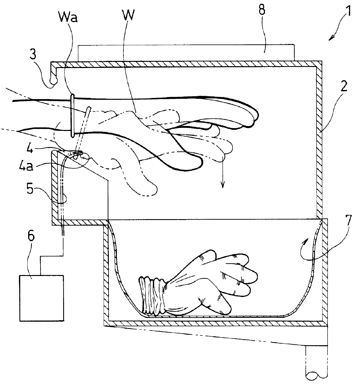
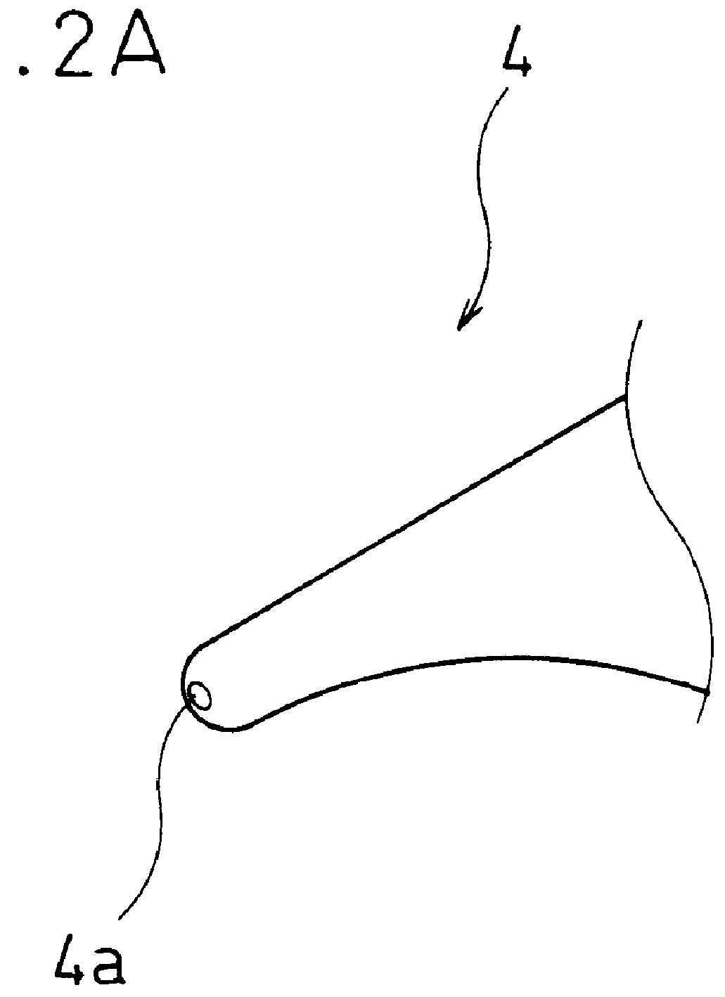
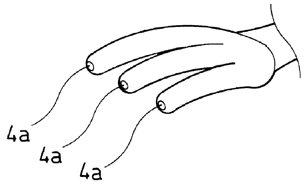
FIG. 1 is a sectional view showing a glove release apparatus according to the present invention. FIG. 2A and FIG. 2B are perspective views showing the structure of an engagement unit.

As shown in FIG. 1, the glove release apparatus 1 comprises a housing 2 having an opening 3, a protrusion 4 as an engagement unit placed near the opening 3, an injection hole 4a formed at the tip of the protrusion 4, a fluid injection device 6 communicated with the injection hole 4a through a supply pipe 5, a storage unit 7 provided at the bottom of the housing 2, and a germicidal lamp 8 at a predetermined portion of the housing 2.

It is preferred that the protrusion 4 has a curved surface as shown in FIG. 2A and that the end portion is formed thin so as to be easily inserted into an insertion opening Wa between a hand and a glove W. Alternatively, as shown in FIG. 2B, the protrusion 4 can be formed as a protrusion 4A having a plurality of branches (in FIG. 2, three). In the case of protrusion 4A, an inj...

second embodiment

Next, the glove release apparatus will be described with reference to FIG. 3.

FIG. 3 is a sectional view of the glove release apparatus according to the second embodiment of the present invention. As shown in FIG. 3, the glove release apparatus 11 comprises a housing 12 having an opening 13, movable protrusions 14 as an engagement unit having an injection hole placed near the opening 13, a switch 19 for operating the protrusions 14, a fluid injection device 16 connected to the injection hole with a pipe 15, a storage unit 17 provided at a space under the housing 12, and a germicidal lamp 18 provided at a predetermined portion of the housing 12. The protrusions 14 may be formed as the one having one protrusion or the one having a plurality of branches as shown in FIG. 2A and FIG. 2B, respectively.

Next, the operation of the glove release apparatus 11 will be described.

As shown in FIG. 3, first, the hand wearing the glove W is inserted into the inner part of the housing 12 and turns on ...

third embodiment

Next, referring to FIG. 4, the glove release apparatus will be described.

FIG. 4 is a sectional view of the glove release apparatus according to the third embodiment of the present invention. As shown in FIG. 4, the glove release apparatus 21 comprises a housing 22 having an opening 23, a protrusion 24 as an engagement unit placed near the opening, 3, a switching mechanism 29 integrated with the protrusion 24, a storage unit 27 provided at a space under the housing 22, and a germicidal lamp 28 provided at a predetermined portion of the housing 22.

The switching mechanism 29 comprises a switch plate 29a and a spring coil 29b provided substantially at the middle of the protrusion 24 and the switch plate 29a. The protrusion 24 always receives the elasticity of the spring coil 29b so as to be in position. A fluid injection device 26 may be provided at the protrusion 24 so that fluid such as air and water from the fluid injection device 26 is injected from the tip of the protrusion 24 thro...


PUM


Abstract

Since surgical gloves contact patients' blood and focuses, there is a possibility of infection, especially the case of Hepatitis B virus and AIDS if hands contact blood on the gloves. Therefore, a glove release apparatus of the present invention is for safely and sanitarily pulling off a glove made of a stretchable material from a hand and comprises a housing having an opening to which the hand wearing the glove is inserted, and an engagement unit for hooking an insertion opening of the glove, please near the opening of the housing. In order to pull off the glove, the hand wearing the glove is inserted into the opening of the housing and the insertion opening of the glove is hooked to the engagement unit. Then, as the hand is moved towards the opening of the housing, the glove is gradually pulled off from the hand.

Description

1. Field of the InventionThe present invention relates to a glove release apparatus and a method for the same, which easily and sanitarily pulls off gloves made of stretchable members such as natural rubber or synthetic rubber from hands.2. Description of Related ArtStretchable gloves are usually used during surgeries. Gloves used in hospitals are made thin so as to fit fingers for delicate operations with medical instruments. There is strict sanitary control for use of gloves since surgeons perform operations on incised body with gloves on. When the surgeon puts on the gloves, hands are washed and brushed with medicated soap and dried with a drier, and then a nurse who already finishes sterilization puts gloves on the surgeon's hands against the elasticity of gloves so that the fingertips of the glove reach the surgeon's fingertips.Further, to pull off the gloves from hands after surgeries, the glove is pulled off with the other hand wearing the glove on and then the other glove is...

Claims


Application Information

Patent Timeline
Patent Type & Authority Patents(United States)
IPC IPC(8): A47G25/00A47G25/90A61B19/04A61B19/00A41D19/00
CPCA47G25/904A61B19/04A61B2019/046A61B42/50A61B42/00
Inventor YONEZAWA, NARIMITSU
Owner YONEZAWA NARIMITSU
Why Eureka
Try Eureka