Drive system for vacuum fluorescent display and method therefor

a fluorescent display and drive system technology, applied in the field of vacuum fluorescent display, can solve the problems of "fuzzy" display, affecting the processing efficiency of the device, and wasting processor tim

Inactive Publication Date: 2000-02-15
PRINCE
View PDF14 Cites 6 Cited by
  • Summary
  • Abstract
  • Description
  • Claims
  • Application Information

AI Technical Summary

Problems solved by technology

One problem often associated with fluorescent display systems having closely spaced anodes is that the thermions emitted by the filament cathode sometimes "bleed" toward anodes that are associated with adjacent non-activated grids and that receive a logic "high" data signal, thus causing a "fuzzy" display.
Even though the anodes 11 associated with inactive grids 14 are not enabled, those anodes are still susceptible to bleeding if they receive a logic "high" data signal from their respective anode drivers.
Although, the above-described method minimizes thermion bleeding, it comes at the expense of processor time.
Therefore, known quad-anode display driving systems have two primary drawbacks that make them inefficient and in some cases expensive to manufacture.
First, the processor must perform an "AND" mask operation, thus utilizing valuable processor time.
To perform these functions in certain applications, as in an automobile environment, a separate dedicated processor typically is desired, as opposed to the on-board processor of the vehicle, thus further adding to the inefficiency and expense of known systems.

Method used


Image

  • Drive system for vacuum fluorescent display and method therefor
  • Drive system for vacuum fluorescent display and method therefor
  • Drive system for vacuum fluorescent display and method therefor

Examples


Embodiment Construction

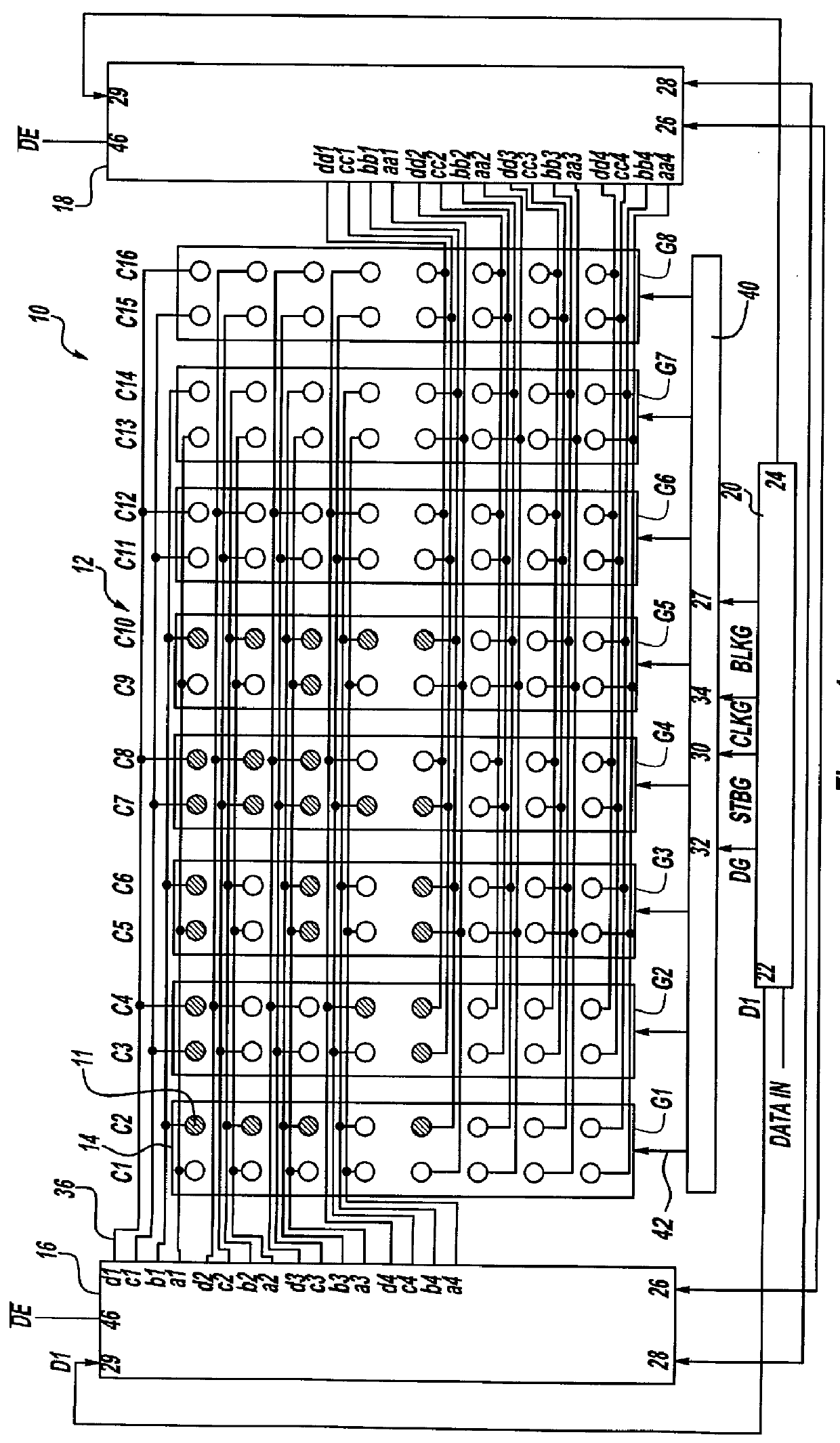
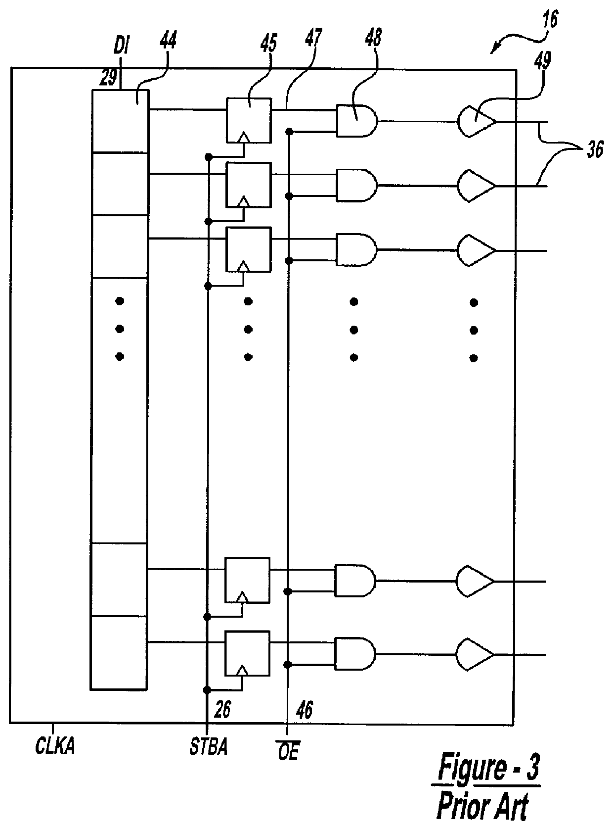
Referring in more detail to the drawings, FIG. 4 shows the principal components of the preferred embodiment of a vacuum fluorescent display (VFD) according to the instant invention that utilizes a quad-matrix method of driving the system 60. In particular, in the preferred embodiment, system 60 of the instant invention includes a first anode driver 62 and a second anode driver 64 for supplying display data to a plurality of anodes 74 arranged in a matrix 61 consisting of rows and columns C1-C16 of anodes 74. Anode drivers 62, 64 are identical to the anode driver shown in FIG. 3 and described previously with respect to the conventional system shown in FIG. 1, and are fabricated in a display module for a VFD.

In addition, system 60 includes a series of grids 65 being positioned between matrix 61 and a plurality of filament cathodes 102 (FIG. 6). Each grid 65 is associated with two columns of anodes 74 of matrix 61 and functions to attract thermions emitted by the cathode toward activat...


PUM


Abstract

The vacuum fluorescent display (VFD) system of the inventive invention includes a display matrix including an array of anodes, a processor, at least two anode drivers, and a grid driver to selectively activate the anodes of the display matrix. The system of the instant invention alternatingly disables some of the output gates of the two anode drivers so that the anodes in the outer columns of anodes associated with the activated grids are, preferably, pulled to ground, while the anodes in the inner columns of anodes of the activated grids may respond to the display data output from the anode driver output gates that are not currently disabled. Preferably, the output lines of each anode driver are connected to particular columns of anodes such that when successive grids are activated, thus enabling particular columns of anodes, at least some of the anode driver output gates are connected to the anodes in the outer columns of anodes in the activated grids, while the other anode driver output gates are connected to the anodes in the inner columns of anodes in the activated grids.

Description

1. Field of the InventionThe present invention relates to vacuum fluorescent display (VFD) systems having a plurality of anodes arranged in a matrix that may be selectively activated to display information. More particularly, the present invention relates to a method of driving a fluorescent display utilizing a quad-anode connection structure between the data drivers and the anodes to produce a high density and high clarity dot matrix display.2. Discussion of Related ArtVacuum fluorescent displays typically include a matrix of anodes that comprise the pixels of the display and at least one filament cathode that is positioned adjacent to the matrix of anodes and parallel to the plane defined by the matrix. When the system is activated, a power source heats the filament cathode, thus causing the filament to emit thermions that, in turn, are attracted toward activated anodes. Because the anodes are coated with a reactive material, the thermions that contact the activated anodes will ca...

Claims


Application Information

Patent Timeline
Patent Type & Authority Patents(United States)
IPC IPC(8): G09G3/22
CPCG09G3/22
Inventor MART, GREGORY A.
Owner PRINCE
Why Eureka
Try Eureka