Emergency location signaling device

a signaling device and emergency location technology, applied in the direction of illumination signalling devices, transportation and packaging, lighter-than-air aircraft, etc., can solve the problems of introducing a certain degree of unreliability and creating installation problems

Inactive Publication Date: 2000-03-07
ASHLINE JUNE THELMA
View PDF17 Cites 26 Cited by
  • Summary
  • Abstract
  • Description
  • Claims
  • Application Information

AI Technical Summary

Problems solved by technology

Such prior art location signaling arrangements often require special craft or vehicle mounting facilities and / or impact responsive release means that create installation problems and introduce a certain degree of unreliability such as unintended trigger.

Method used


Image

  • Emergency location signaling device
  • Emergency location signaling device
  • Emergency location signaling device

Examples


Embodiment Construction

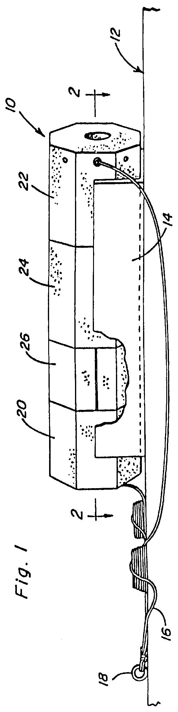
Referring now to the drawings in detail, FIG. 1 illustrates a typical emergency location indicating unit constructed in accordance with the present invention, and generally referred to by reference numeral 10. The unit is shown carried on some vehicle or craft 12, by means of a holding rack 14 from which the unit may be removed for servicing. Further, the unit may be loosely anchored to the craft 12 by means of a cable 16 secured to some anchoring hardware 18.

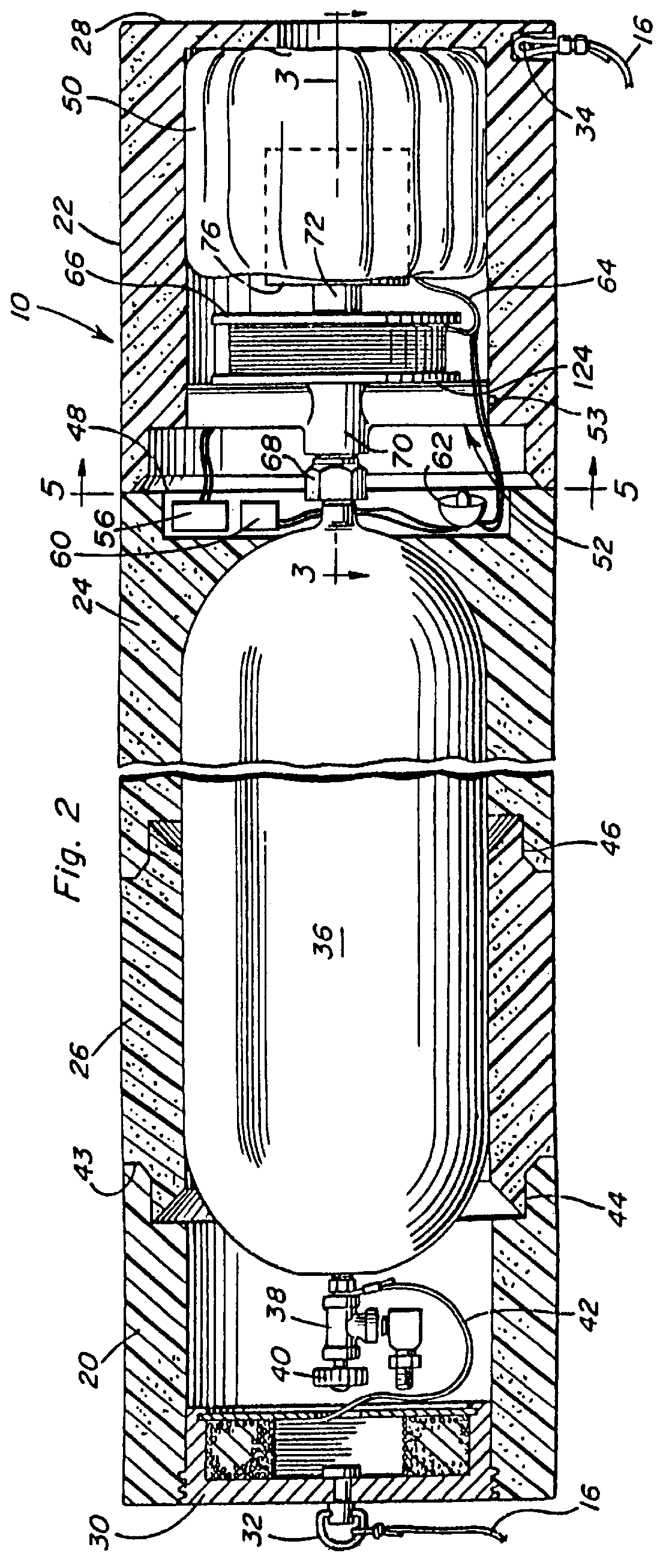
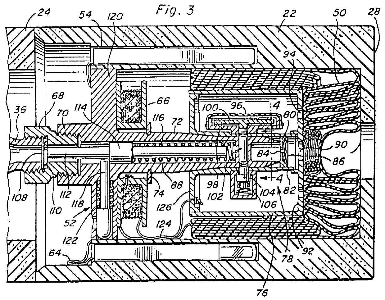
The unit 10 has an outer package housing launching guide assembly, formed by axial end closure members 20 and 22, intermediate flotation positioning means in the form of a support collar 24 and a plurality of separable breakaway housing sections 26 held assembled between the end closure 20 and the flotation collar 24. In the illustrated embodiment, the housing assembly has an octagonal outer cross-section and forms a tubular enclosure between an end wall 28 of closure 22 and a cable storing plug member 30 of closure 20 as shown...


PUM


Abstract

An aerial lift balloon and signaling components attached thereto are stored within a closure member held assembled with a breakaway housing to form a package storing an inflating device for the balloon. Removal of the closure member initiates inflation of the balloon and operation of the signaling components, while removal of an end cover of the package permits separation of the breakaway housing enabling the positioning of the inflating device by a flotation collar portion of the package for aerial launching of the balloon. A stroboscopic light suspended between the floatation collar and the aerial lift balloon provides enhanced visibility of the signal device.

Description

BACKGROUND OF THE INVENTIONThis invention relates to emergency location signaling devices of the type disclosed in my prior U.S. Pat. No. 4,433,638, incorporated herein by reference in its entirety, with respect to which the present invention is an improvement.Location marking devices that are automatically released, launched and triggered into operation are well known as shown in my prior U.S. Pat. Nos. 3,253,573 and 3,332,390. The automatic release of a marker buoy anchored to a submerged craft, and from which an aerial balloon is launched, is shown in U.S. Pat. No. 2,470,783 to Mead. Also known are radio and light signaling components suspended from an inflated balloon anchored by a cable to its storage enclosure, as shown in U.S. Pat. No. 2,923,917 to McPherson. Other location signaling devices are shown in U.S. Pat. Nos. 2,821,725 and 4,102,296.Such prior art location signaling arrangements often require special craft or vehicle mounting facilities and / or impact responsive rele...

Claims


Application Information

Patent Timeline
Patent Type & Authority Patents(United States)
IPC IPC(8): B63C7/26B63C7/00B64B1/00B64B1/50
CPCB63C7/26B64B1/50B63B2201/08B63B2201/12B63B2201/14Y10S116/09
Inventor ASHLINE, CLIFFORD E.
Owner ASHLINE JUNE THELMA
Why Eureka
Try Eureka