Spot welding system

a welding system and spot welding technology, applied in the direction of soldering apparatus, welding devices, manufacturing tools, etc., can solve the problems of occupying space, arranging the articulated robots close, and unable to take advantage of a high-density layout for improving operational efficiency and saving space. , to achieve the effect of saving space and improving spot welding efficiency

Inactive Publication Date: 2000-05-09
FANUC LTD
View PDF10 Cites 34 Cited by
  • Summary
  • Abstract
  • Description
  • Claims
  • Application Information

AI Technical Summary

Benefits of technology

An object of the present invention is to provide a spot welding system in which a plurality of r

Problems solved by technology

However, in the conventional spot welding system using articulated robots encompass problems in efficiency of operation and space utilization.
Specifically, it is difficult to arrange the articulated r

Method used


Image

  • Spot welding system
  • Spot welding system
  • Spot welding system

Examples


Embodiment Construction

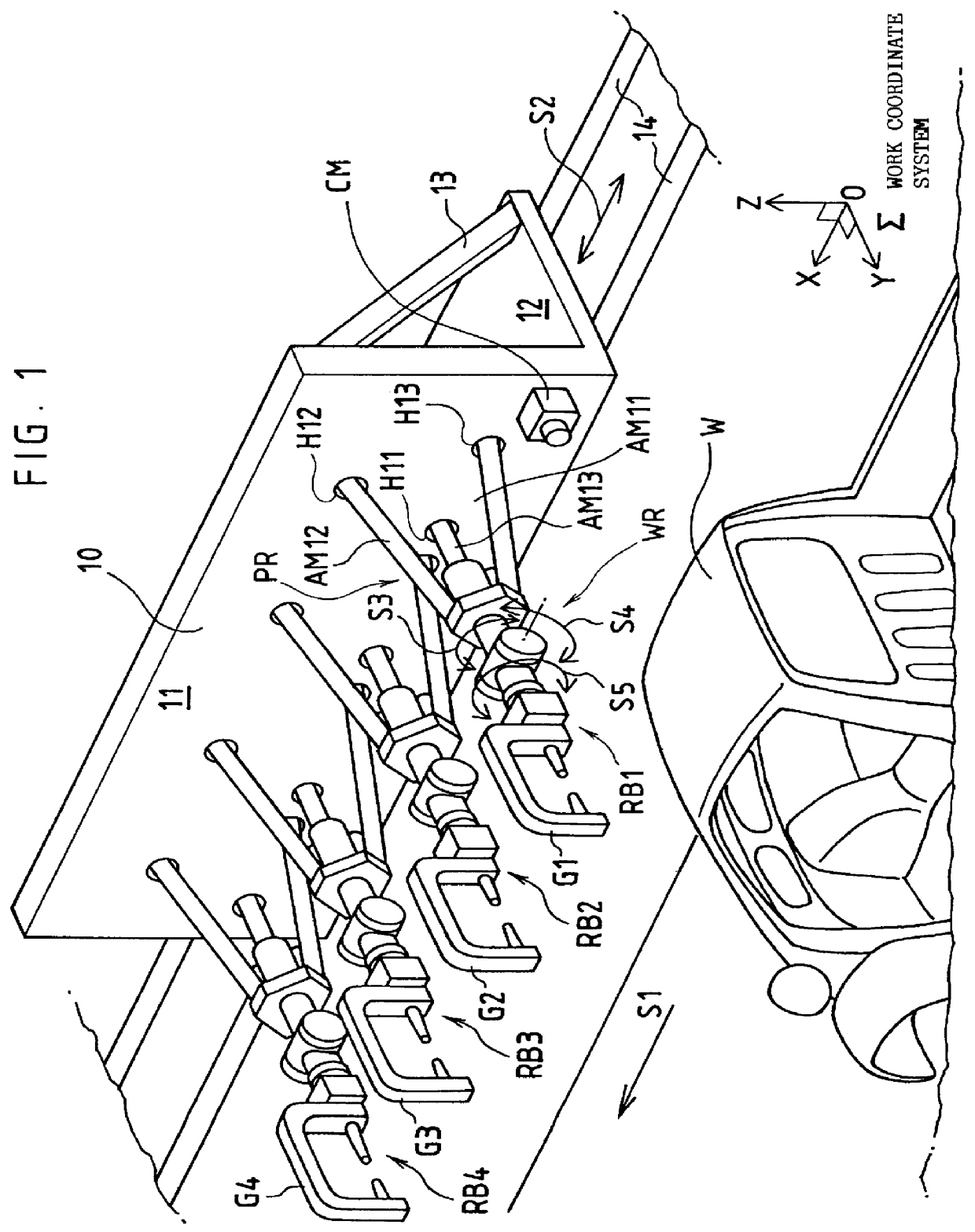
In FIG. 1, a reference symbol S1 denotes a traveling direction of a conveyor (not shown) for conveying a workpiece (e.g., an unfinished automobile body assembly) W, and the traveling direction coincides with a X-axis direction of a work coordinate system .SIGMA.. Guides 14 are laid on a structure such as a floor along the traveling direction of the conveyor, and a frame 10 is movably mounted on the guides 14 in a direction indicated by an arrow S2.

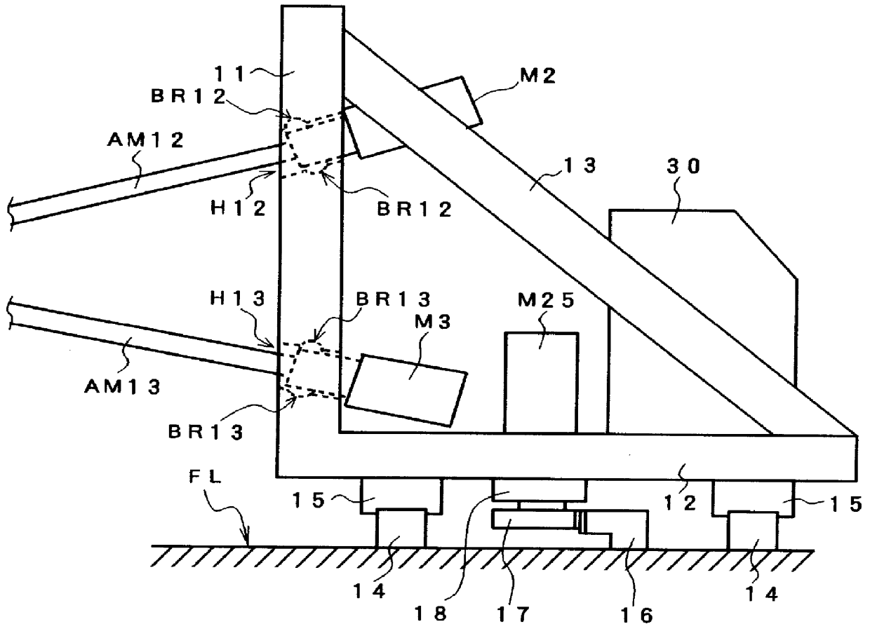
The frame 10 comprises an upright wall portion 11 and a base portion 12 in L-shape, and reinforcing members 13. A camera CM for detecting a location of the workpiece W is disposed at an appropriate position on the upright wall portion 11. The camera CM constitutes a visual sensor together with an image processing unit incorporated in a controller, which is described later, and is used for tracking operations of the robots.

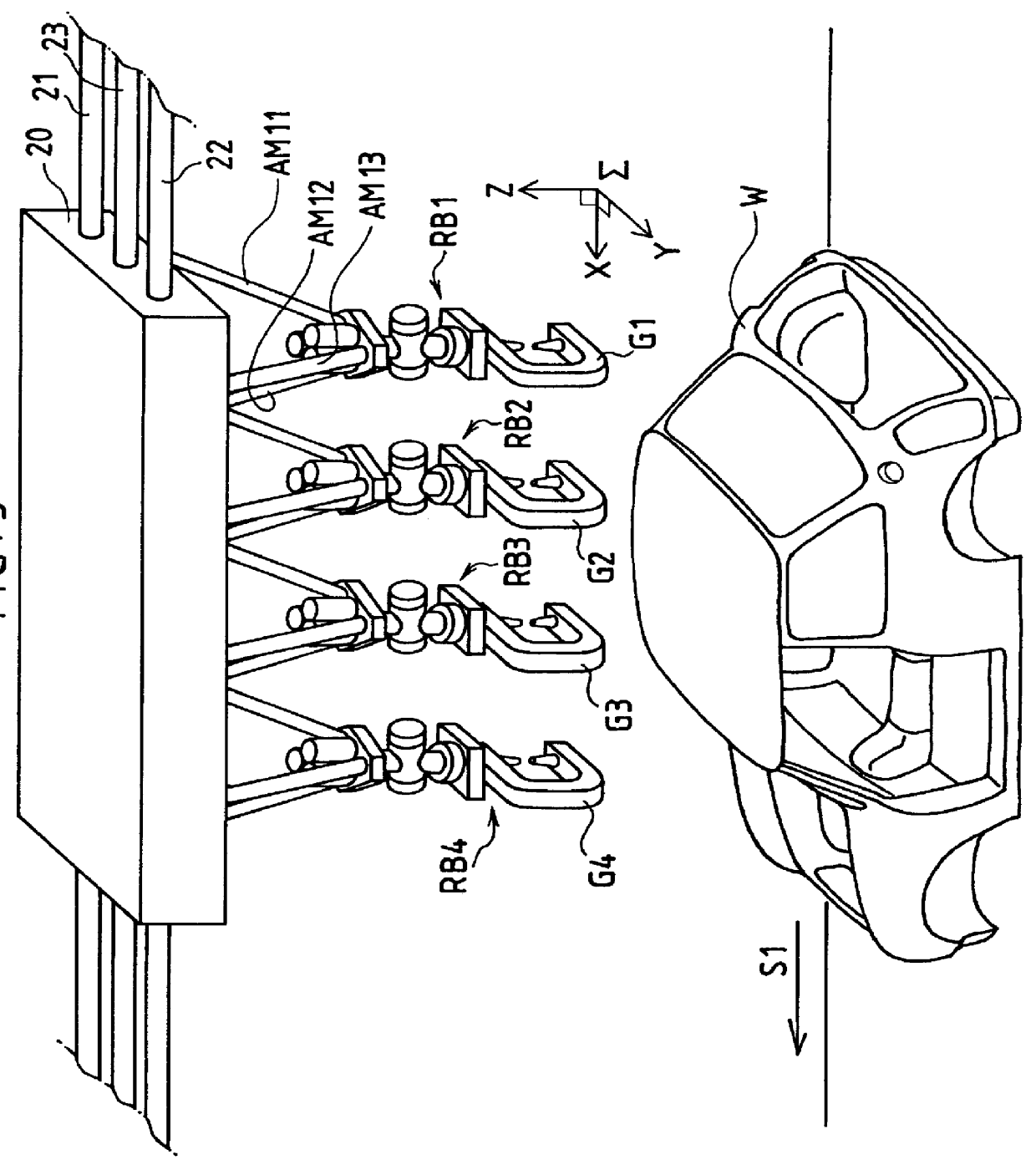
A plurality of parallel link robots RB1-RB4 are densely arranged in a row on the frame 10 along the traveling direction...


PUM


Abstract

PCT No. PCT/JP97/01462 Sec. 371 Date Dec. 22, 1997 Sec. 102(e) Date Dec. 22, 1997 PCT Filed Apr. 25, 1997 PCT Pub. No. WO97/39853 PCT Pub. Date Oct. 30, 1997A spot welding system employing parallel link robots arranged densely with one another. When an arrival of a workpiece W being conveyed is detected by a camera CM, a frame moves along guides to start tracking of the workpiece, and a plurality of robots RB1-RB4, each having a parallel link with a plurality of expandable/retractable arms and a wrist mounted on a distal end of the parallel link, start operation. A plurality of points on the workpiece are welded by spot welding guns G1-G4 attached to the wrists of the respective robots. Proximal end portions of the expandable/retractable arms are swingably supported by an upright wall of the frame, and the respective robots are disposed so as to project from the frame. The parallel link robots may be suspended from the frame to be arranged densely.

Description

The present invention relates to a spot welding system using robots.Spot welding systems using robots with spot welding guns are well known and widely adopted in an assembling process of an automobile body, for example. In general, the spot welding is not carried out only on a single welding spot but is practically carried out on a number of welding spots, especially in the assembling process of an automobile body.Thus, in conventional spot welding systems, there is adopted a layout in which a plurality of articulated robots are arranged in a row to laterally project from an upright wall or to be suspended from a structure such as a ceiling or a beam. In some cases, instead of using an existing structure, a frame dedicated for installing robots is provided.An object of welding such as an automobile body is transferred along a line which passes near the robots arranged in a row. Usually, the transferring action is intermittently repeated to stop successively at respective operating s...

Claims


Application Information

Patent Timeline
IPC IPC(8): B23K11/31B23K11/30B23K37/047B23K11/11
CPCB23K37/047B23K11/314
Inventor NIHEI, RYOOKADA, TAKESHI
Owner FANUC LTD
Why Eureka
Try Eureka