Efficiency workpiece point welding machine

A spot welding machine, high-efficiency technology, applied in welding equipment, manufacturing tools, resistance welding equipment, etc., can solve the problems of low precision, low spot welding efficiency, complex structure, etc., achieve high welding efficiency, improve spot welding quality, Good clamping firmness

Inactive Publication Date: 2019-04-02
马鞍山迪斯福工业设计有限公司
View PDF6 Cites 1 Cited by
  • Summary
  • Abstract
  • Description
  • Claims
  • Application Information

AI Technical Summary

Problems solved by technology

[0003] The workpiece spot welding machine in the prior art has complex structure, low spot welding efficiency and low precision, therefore, it is necessary to improve

Method used


Image

  • Efficiency workpiece point welding machine
  • Efficiency workpiece point welding machine

Examples


Embodiment Construction

[0019] The technical solutions in the embodiments of the present invention will be clearly and completely described below in conjunction with the accompanying drawings in the embodiments of the present invention. Obviously, the described embodiments are only a part of the embodiments of the present invention, rather than all the embodiments. Based on the embodiments of the present invention, all other embodiments obtained by those of ordinary skill in the art without creative work shall fall within the protection scope of the present invention.

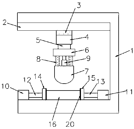
[0020] See Figure 1-2 , The present invention provides a technical solution: a high-efficiency spot welding machine for workpieces, comprising a U-shaped bracket 1, a horizontal slide rail 2 is fixedly installed inside the upper end of the U-shaped bracket 1, and a second horizontal slide rail 2 is installed in the horizontal slide rail 2 A slider 3, the first slider 3 is installed on the upper end of the longitudinal slide rail 4, a se...


PUM

PropertyMeasurementUnit
thicknessaaaaaaaaaa

Abstract

The invention discloses an efficiency workpiece point welding machine. The efficiency workpiece point welding machine comprises a u-shaped bracket. A transverse sliding rail is fixedly mounted on theinner side of the upper end of the u-shaped bracket. A first sliding block is mounted in the transverse sliding rail. The first sliding block is mounted at the upper end of a longitudinal sliding rail. A second sliding block is mounted in the longitudinal sliding rail. A welding head mounting seat is mounted on the second sliding block. A welding head is mounted below the welding head mounting seat. Two sets of buffer springs are arranged between the upper end of the welding head and the lower end of the welding head mounting seat. A guide assembly is mounted between the two sets of buffer springs. A workpiece placing mechanism is mounted on the inner side of the u-shaped bracket. The physical design is novel. A workpiece can be welded transversely and longitudinally. The workpiece placingmechanism is arranged to clamp workpieces of different sizes. It is unnecessary to replace the whole placing mechanism, and therefore the point welding efficiency can be improved.

Description

Technical field [0001] The invention relates to the technical field of spot welding machines, in particular to a high-efficiency workpiece spot welding machine. Background technique [0002] The spot welding machine adopts the principle of double-sided double-point overcurrent welding. When working, the two electrodes pressurize the workpiece so that the two layers of metal form a certain contact resistance under the pressure of the two electrodes, and the welding current flows from one electrode to the other electrode At the two contact resistance points, an instantaneous thermal fusion is formed, and the welding current flows from the other electrode along the two workpieces to this electrode to form a loop without damaging the internal structure of the welded workpiece. The welding machine uses the high-temperature arc generated by the positive and negative poles in an instant short circuit to melt the solder and the material to be welded on the electrode to achieve the purpos...

Claims


Application Information

Patent Timeline
Patent Type & Authority Applications(China)
IPC IPC(8): B23K11/11B23K11/36
CPCB23K11/11B23K11/36
Inventor 姜海燕陶建查
Owner 马鞍山迪斯福工业设计有限公司
Why Eureka
Try Eureka