
Stripping device for integrated circuit (IC) chip

A stripping device and chip technology, applied in the manufacturing of electrical components, circuits, semiconductor/solid-state devices, etc., can solve problems such as difficulty in implementation, impact on production efficiency, inability to measure the force of the chip, etc., achieve high linear motion accuracy, avoid impact, The effect of increasing peel reliability

Active Publication Date: 2013-09-18
HUAZHONG UNIV OF SCI & TECH
View PDF4 Cites 31 Cited by
  • Summary
  • Abstract
  • Description
  • Claims
  • Application Information

AI Technical Summary

Problems solved by technology

[0004] Patent document 200510108938.6 only discusses the material and related structural features of the thimble, and does not involve the research on the entire process of thimble work; The Euler critical load makes it have preset buckling characteristics, that is, when the preset rated jacking force is reached, the thimble buckles to protect the chip, but this technology is actually difficult to implement and has not been used in actual mass production; The patent document CN101707181A reduces the impact on the semiconductor chip by reducing the speed of the ejector pin, but this solution has a certain impact on the production efficiency, and the force on the chip cannot be measured

Method used


Image

  • Stripping device for integrated circuit (IC) chip
  • Stripping device for integrated circuit (IC) chip
  • Stripping device for integrated circuit (IC) chip

Examples


Embodiment Construction

[0033] In order to make the object, technical solution and advantages of the present invention clearer, the present invention will be further described in detail below in conjunction with the accompanying drawings and preferred embodiments. It should be understood that the specific embodiments described here are only used to explain the present invention, not to limit the present invention.

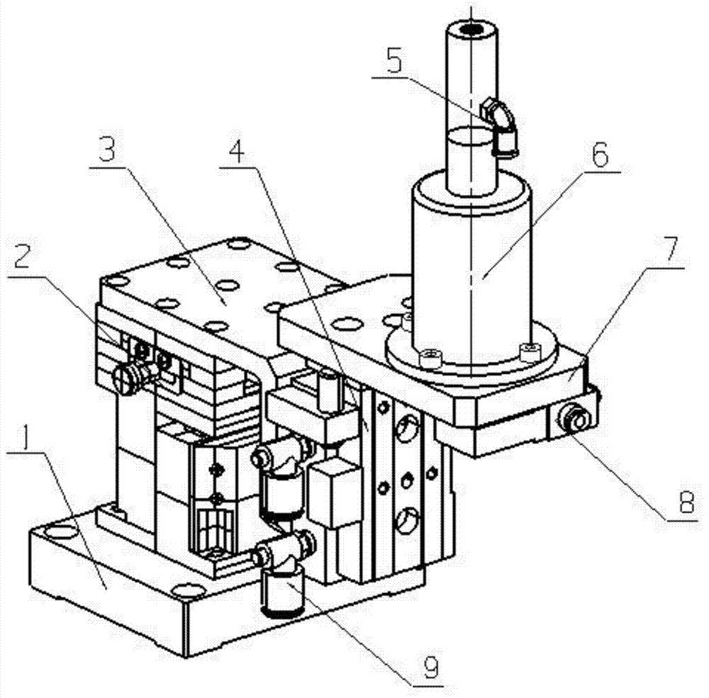
[0034] see figure 1 , a preferred embodiment of an IC chip safety stripping device of the present invention, including a mounting plate 1, a position adjustment mechanism 2, a sliding table mounting plate 3, a sliding table mechanism 4, an adsorption air pipe joint 5, a thimble mechanism 6, and a thimble mechanism mounting plate 7. Vacuum generator 8 and air pipe joint 9 of slide table. The mounting plate 1 is used to install the entire chip stripping device on the production equipment; the position adjustment mechanism 2 is mounted on the mounting plate 1 and is used for fine-tuning the...


PUM


Abstract

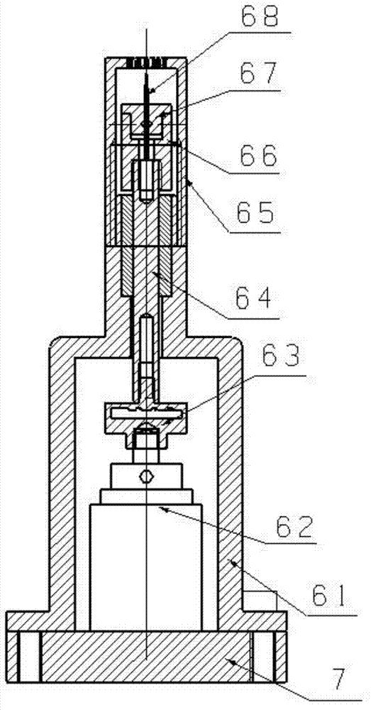
The invention discloses a stripping device for an integrated circuit (IC) chip. The device comprises a mounting plate, a position regulation mechanism, a sliding table mechanism, an ejector pin mechanism and a vacuum generator. The ejector pin mechanism comprises a sleeve, a linear motor, a linear transmission mechanism, a force sensor, an ejector pin seat, an ejector pin clamping piece and an ejector pin, wherein the sleeve is arranged on a sliding table; the linear motor is arranged in the sleeve, and the control end of the linear motor is connected with the output end of an external control center; the linear transmission mechanism is arranged in the sleeve, and the lower end of the linear transmission mechanism is connected with an output shaft of the linear motor; the force sensor is arranged between the output shaft of the linear motor and the linear transmission mechanism, and the signal output end of the force sensor is connected with the input end of the external control center; the ejector pin seat is arranged at the top of the sleeve; an air hole is formed in the surface of the ejector pin seat; the ejector pin seat is connected with an air tube of the vacuum generator through the air hole; the ejector pin clamping piece is arranged in the ejector pin seat, and is connected with the upper end of the linear transmission mechanism; and the ejector pin is clamped through the ejector pin clamping piece. A closed loop force control scheme is adopted, and the chip is stripped on the premise of no damage to the chip, so that the device has the characteristics of safety, high efficiency and high stripping reliability.

Description

technical field [0001] The invention relates to the technical field of packaging of semiconductor chips, in particular to an IC chip safety stripping device, which is used for lifting the chip from a wafer blue film bonded with the IC chip in the chip assembly process of the IC packaging technology. Background technique [0002] The integrated circuit (IC) industry seems to be the high-speed growth point of today's global economic development, the most dynamic part of my country's national economy, and a basic and strategic industry related to national economic and social development. Electronic packaging, as the last process of the IC industry, connects and fixes the IC chip that has passed the electrical test to other devices, and then fixes it to the shell or substrate, so as to form a device with specific functions and put it into practical application. The chip pick-up process is an indispensable key process step in electronic packaging. It completes the first transfer ...

Claims


Application Information

Patent Timeline
Patent Type & Authority Applications(China)
IPC IPC(8): H01L21/67H01L21/68
Inventor 陈建魁尹周平范守元黄永安付宇
Owner HUAZHONG UNIV OF SCI & TECH
Learn More