Rotatable seal element for a rotary machine

a technology of rotary machines and seal elements, which is applied in the field of rotary machines, can solve problems such as slow crack growth, and achieve the effect of predicting the minimum cyclic life of the seal assembly

Inactive Publication Date: 2000-07-04
UNITED TECH CORP
View PDF3 Cites 8 Cited by
  • Summary
  • Abstract
  • Description
  • Claims
  • Application Information

AI Technical Summary

Benefits of technology

A primary advantage of the present invention is the cyclic fatigue life of a seal element which results from the geometry of the interface between adjacent rings that causes cracks that form to have to grow in more than one lateral direction at the interface between the rings. Another advantage of the present invention is the predictability of the minimum

Problems solved by technology

This is particularly critical if a horizontal crack exists which extends from one free side of the structure to another free

Method used


Image

  • Rotatable seal element for a rotary machine
  • Rotatable seal element for a rotary machine
  • Rotatable seal element for a rotary machine

Examples


Embodiment Construction

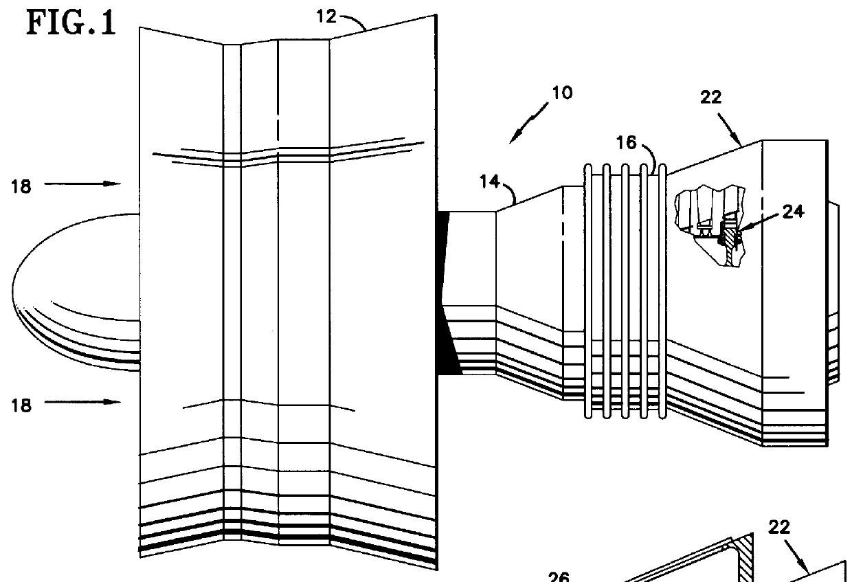
FIG. 1 is a side elevation view of an axial flow rotary machine 10. The rotary machine includes a compression section 12 a combustion section 14 and a turbine section 16. A flowpath for working medium gases 18 extends axially through the sections of the engine. a stator assembly 22 extends axially through the engine outwardly of the flowpath to bound the flowpath for working medium gases. A rotor assembly 24 is disposed inwardly of the flowpath for working medium gases.

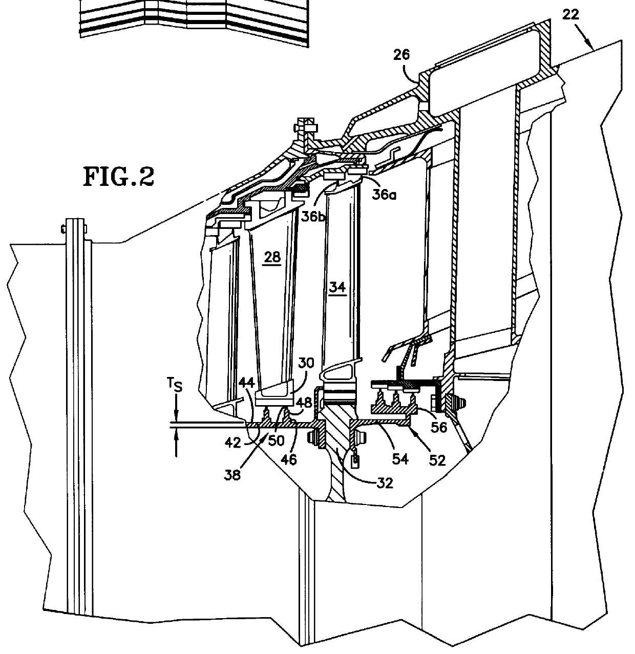
FIG. 2 is an enlarged view of a portion of the turbine section 16 shown in FIG. 1. The stator assembly 22 includes an outer case 26 and a plurality of stator vanes 28 which extend radially inwardly across the working medium flowpath. The stator vanes are connected by a plurality of circumferentially extending seal land 30 which are spaced radially outwardly of the rotor assembly. The seal land is circumferentially continuous.

The rotor assembly 24 includes a rotor disk 32 and a plurality of rotor blades 34. The rotor b...


PUM


Abstract

A rotatable seal element 38 is formed of at least two circumferentially continuous rings 48,50. The rings have decreased thickness T.sub.2, T.sub.3 in the outward direction. Various construction details are developed which effect the level of cyclic fatigue life. In one particular embodiment, the seal element has a flat surface 74 extending inwardly from the sides at the interface between the rings.

Description

TECHNICAL FIELDThis invention relates to a rotary machine having a working medium flowpath and a rotatable seal element which extends circumferentially about an axis of rotation. More particularly, this invention relates to seal elements formed of a plurality of stacked rings. It has particular application to gas turbine engines to block the leakage of working medium gases at the boundary of the working medium flowpath.BACKGROUND OF INVENTIONOne example of a rotary machine is a gas turbine engine. The gas turbine engine has a rotor assembly which extends axially through the engine. A stator assembly extends circumferentially about the rotor assembly. A flowpath for working medium gases extends through the engines through the rotor assembly and the stator assembly and is bounded by elements of both assemblies.The rotor assembly typically includes a rotor disk and a plurality of rotor blades extending radially outwardly across the working medium flowpath. The stator assembly includes ...

Claims


Application Information

Patent Timeline
IPC IPC(8): F16J15/48F16J15/46F01D11/02
CPCF01D11/02F05D2250/00Y02T50/60
Inventor PETERS, GARY P.JOHANNUS, ROBERT GERARD
Owner UNITED TECH CORP
Why Eureka
Try Eureka