Tool for chip removing machining

a technology for removing tools and cutting tools, applied in the direction of manufacturing tools, cutting inserts, shaping cutters, etc., can solve the problems of poor transverse stability of inserts and inability to achieve surface contact in connection,

Inactive Publication Date: 2000-07-11
SANDVIK INTELLECTUAL PROPERTY AB
View PDF12 Cites 78 Cited by
  • Summary
  • Abstract
  • Description
  • Claims
  • Application Information

AI Technical Summary

Problems solved by technology

A general disadvantage of such previously known tools is that the inserts have a poor transverse stability since they are rather easily dislodged from a desired position due to the action of transverse forces.
Such a surface contact will not be successfully realized in connection with the manufacturing technique of the modern engineering industry.

Method used


Image

  • Tool for chip removing machining
  • Tool for chip removing machining
  • Tool for chip removing machining

Examples


Embodiment Construction

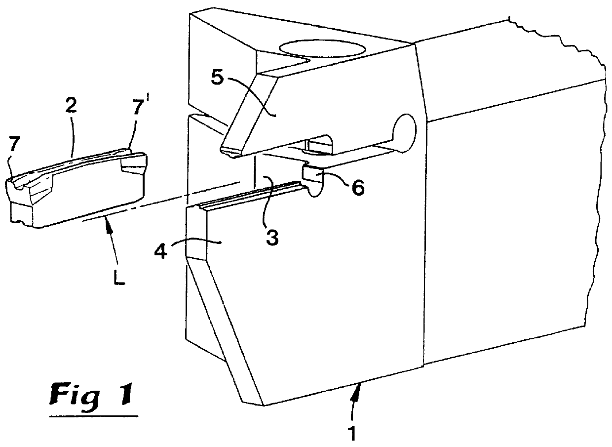
The tool shown in FIG. 1 includes, on one hand, at least a partly blade-shaped insert holder 1 and, on the other hand, an interchangeable cutting insert 2. The cutting insert is mountable in an insert seat 3 in the form of a slot extending in a longitudinal direction L, a bottom of which is defined by a stiff front base portion 4 of the holder, and a top of which is defined by an elastically flexible arm 5 intended to clamp the insert in the insert seat. At an inner end of the insert seat there is an abutment surface 6 that the insert is intended to contact in the active operative position. Preferably, but not necessarily, the insert is of an indexable type since it includes cutting edges 7, 7' at opposite ends. The cutting insert is manufactured from a material that is harder than the material of the insert holder. In practice, cemented carbide is preferred for the cutting insert 2 and steel for the insert holder 1.

The insert is attached to the holder via upper and lower interfaces...


PUM

PropertyMeasurementUnit
obtuse anglesaaaaaaaaaa
acute anglesaaaaaaaaaa

Abstract

A tool for chip-removing machining includes an insert holder and an insert that is mechanically connected with the holder via upper and lower interfaces. Each interface includes a pair of contact surfaces that extend at an obtuse angle relative to each other. Disposed centrally between one of those pairs of contact surfaces is a ridge, and disposed centrally between the other pair of contact surfaces there is a flute. Each of the recess and flute is defined by side surfaces that extend at an acute angle relative to each other. When the ridge engages the flute, a proper absorption of transverse forces acting upon the insert is guaranteed, whereby the insert is maintained essentially immovable in its position in order to guarantee a proper machining accuracy.

Description

This invention relates to a tool for chip removing machining, comprising a blade-shaped insert holder of a first material and an insert manufactured from a different, harder material. The insert is mountable in an outwardly opening recess in the holder, said recess being defined between a lower, stiff front portion of the holder and an upper, elastically flexible arm intended to clamp the insert in the recess. The insert is mechanically connectable with the holder via upper and lower interfaces. At least one of the interfaces includes a male part and a female part. The male means is generally V-shaped in cross-section, and has two laterally separated, first contact surfaces that extend at an obtuse angle relative to each other. The female means is likewise generally V-shaped in cross-section, and includes two laterally separated, second contact surfaces that extend at an obtuse angle relative to each other in order to be brought into contact with the first contact surfaces when the ...

Claims


Application Information

Patent Timeline
Patent Type & Authority Patents(United States)
IPC IPC(8): B23B27/04B23B27/00B23B27/16
CPCB23B27/04B23B2205/02Y10T407/229Y10T407/2288Y10T407/25Y10T407/2292
Inventor HANSSON, PERBRASK, KARL-GORANTAGTSTROM, PERANDERSSON, CLAESHEDBERG, ANNA
Owner SANDVIK INTELLECTUAL PROPERTY AB
Why Eureka
Try Eureka