Device for monitoring the diameter of an orbitally mobile cylindrical piece during machining thereof

Inactive Publication Date: 2000-07-18
ETAMIC
View PDF9 Cites 53 Cited by
  • Summary
  • Abstract
  • Description
  • Claims
  • Application Information

AI Technical Summary

Benefits of technology

It will be understood that by synchronizing the motion of the measuring instrument frame with the motion of the tool, the measuring instrument, or more exactly the member whereby its support bears against the piece, is placed in a fra

Problems solved by technology

However, the means that it implements suffer from major drawbacks in applications where machining time constitutes a non-negligible factor

Method used


Image

  • Device for monitoring the diameter of an orbitally mobile cylindrical piece during machining thereof
  • Device for monitoring the diameter of an orbitally mobile cylindrical piece during machining thereof
  • Device for monitoring the diameter of an orbitally mobile cylindrical piece during machining thereof

Examples


Embodiment Construction

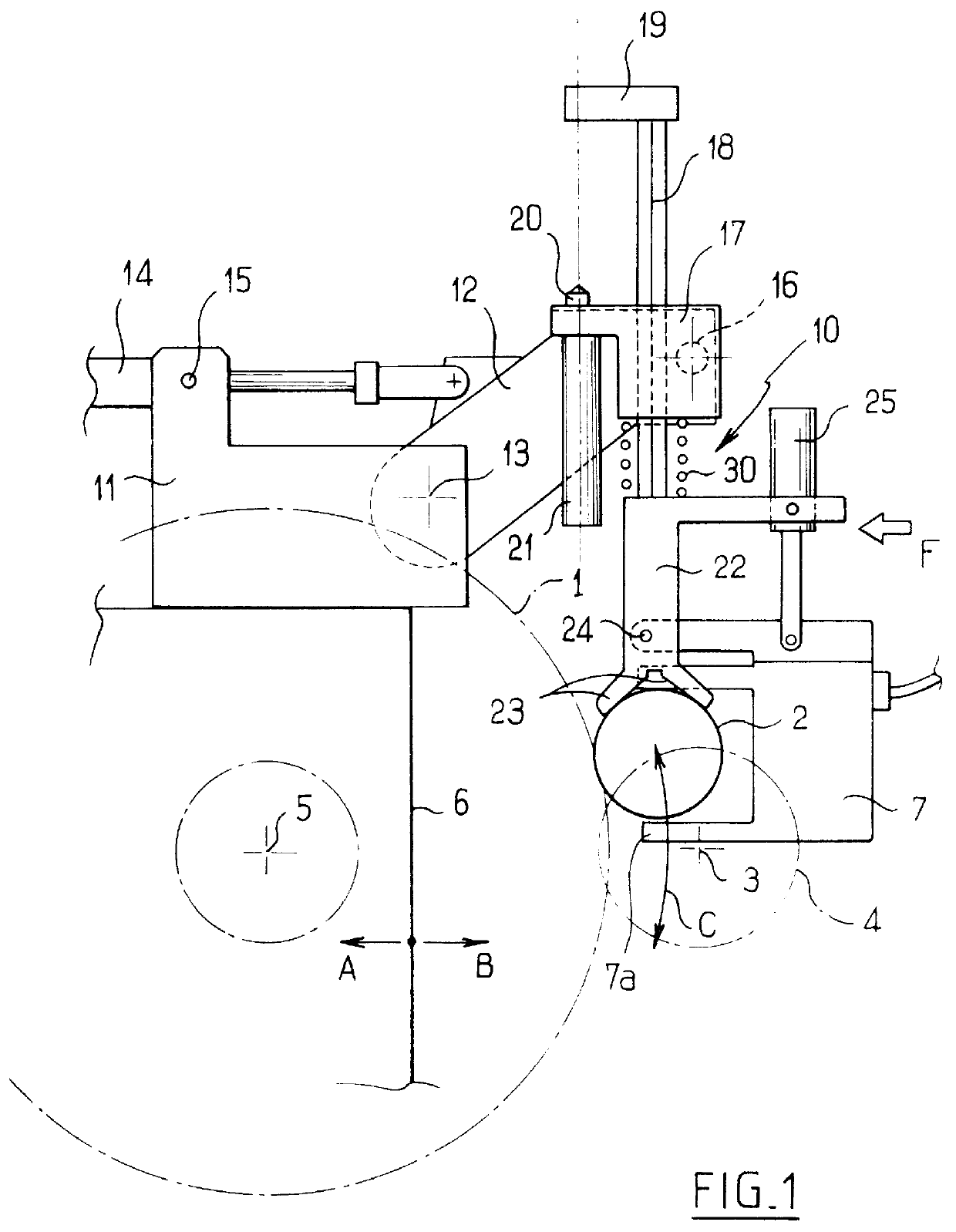
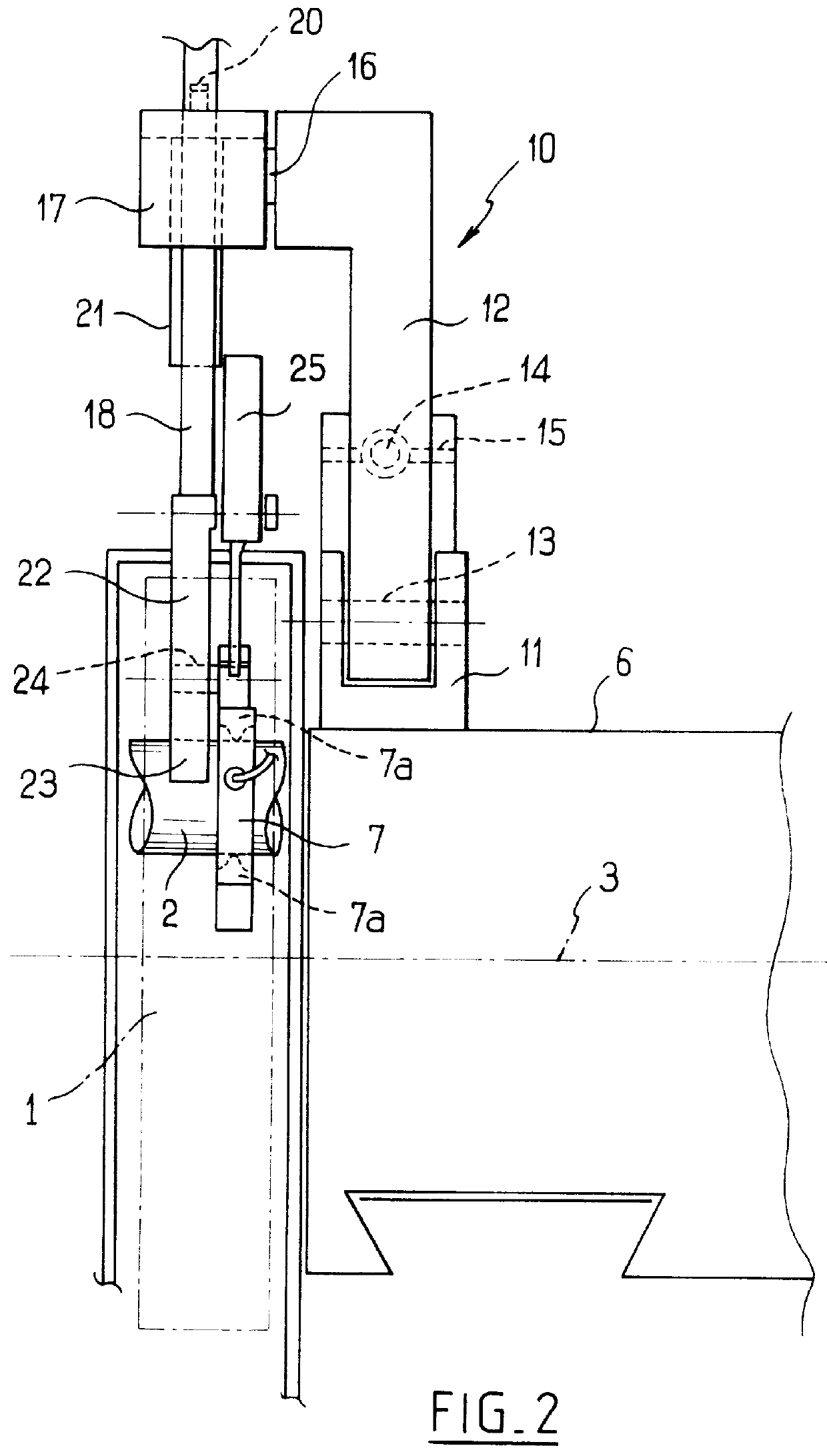
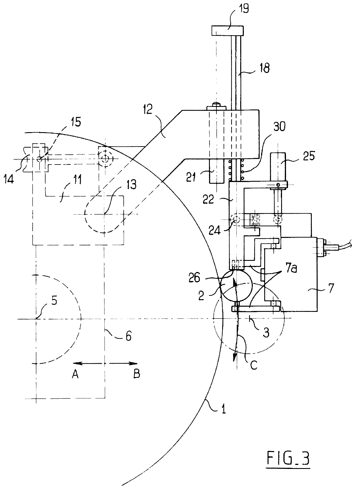
In the examples described below, the invention is applied to using a wheel 1 to grind a crank pin 2 of a crank shaft whose axis of rotation is referenced 3 in the figures. The axis of rotation 3 of the crank shaft is held relative to the frame of the machine (not shown), and the pin 2 describes orbital motion about said axis 3 as symbolized by the circle 4 described by the center of the pin 2.

The grindwheel 1 is mounted to rotate about an axis 5 carried by a carriage 6 which moves with reciprocating motion AB orthogonally to the axis 3. The angular position of the pin 2 relative to the axis 3 and the position of the axis 5 relative to the axis 3 are servo-controlled as a function of a determined grinding program.

The diameter of the pin is inspected in conventional manner by a measurement head 7 which possesses feelers at the end of a fork 7a serving to deliver a signal representative of the diameter of the pin 2. The measurement head is known per se and is available on the market.

Th...


PUM


Abstract

PCT No. PCT/FR96/01545 Sec. 371 Date Mar. 31, 1998 Sec. 102(e) Date Mar. 31, 1998 PCT Filed Oct. 6, 1996 PCT Pub. No. WO97/13614 PCT Pub. Date Apr. 17, 1997A device for measuring and/or checking the diameter of a cylindrical part (2) moving orbitally about an axis (3) during a grinding process. The device comprises a measuring head (7) coupled to a holder (18, 22) which is provided with a member (26) for engaging the circumference of the part (2), and is movably mounted in a direction parallel to itself on a frame (31) so that it can follow the orbital motion of the part (2). Grinding is performed by means of a tool (1) moving transversely to said axis (3), and the frame (31) is moved transversely to said axis and synchronised with the motion of the tool (1).

Description

The present invention relates essentially, but not exclusively, to inspecting the diameter dimension of crank pins while they are being ground.A device for performing that type of inspection is known, in particular from document (FR 2 567 058). However, the means that it implements suffer from major drawbacks in applications where machining time constitutes a non-negligible factor in the cost price of the pieces being machined. With the known device it is necessary to stop the crank shaft rotating and to put the apparatus manually into contact with the crank pin that is to be inspected. Even if the operation of putting the inspection apparatus into contact with the crank pin were to be automated, and likewise the taking out of contact thereof, it would still be necessary to stop the rotating crank shaft in a determined angular position. That known apparatus therefore gives rise to a loss of productivity when grinding crank pins.OBJECTS AND SUMMARY OF THE INVENTIONTo mitigate that dr...

Claims


Application Information

Patent Timeline
IPC IPC(8): B23Q17/20B24B5/42B24B49/04B24B5/00B24B49/02
CPCB23Q17/20B24B5/42B24B49/04B24B49/045
Inventor ESTEVE, XAVIER
Owner ETAMIC
Why Eureka
Try Eureka