Stiffener assembly for bumper system of motor vehicles

a technology for bumper systems and motor vehicles, applied in the direction of bumpers, vehicle components, pedestrian/occupant safety arrangements, etc., can solve the problem of the lower leg of the pedestrian bending under the motor vehicl

Inactive Publication Date: 2000-07-18
FORD GLOBAL TECH LLC
View PDF41 Cites 50 Cited by
  • Summary
  • Abstract
  • Description
  • Claims
  • Application Information

AI Technical Summary

Problems solved by technology

Although the above bumper system has worked well, it suffers from the disadvantage that when a ped

Method used


Image

  • Stiffener assembly for bumper system of motor vehicles
  • Stiffener assembly for bumper system of motor vehicles
  • Stiffener assembly for bumper system of motor vehicles

Examples


Embodiment Construction

)

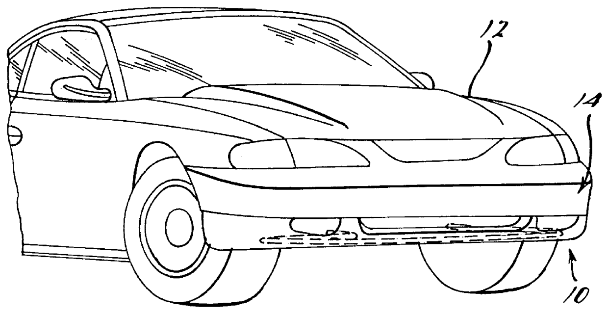
Referring to the drawings and in particular FIG. 1, one embodiment of a stiffener assembly 10, according to the present invention, is illustrated in operational relationship with a motor vehicle 12. The motor vehicle 12 includes a bumper system, generally indicated at 14, at a front or forward end of the motor vehicle 12. It should be appreciated that the stiffener assembly 10 is disposed below the bumper system 14 for a function to be described.

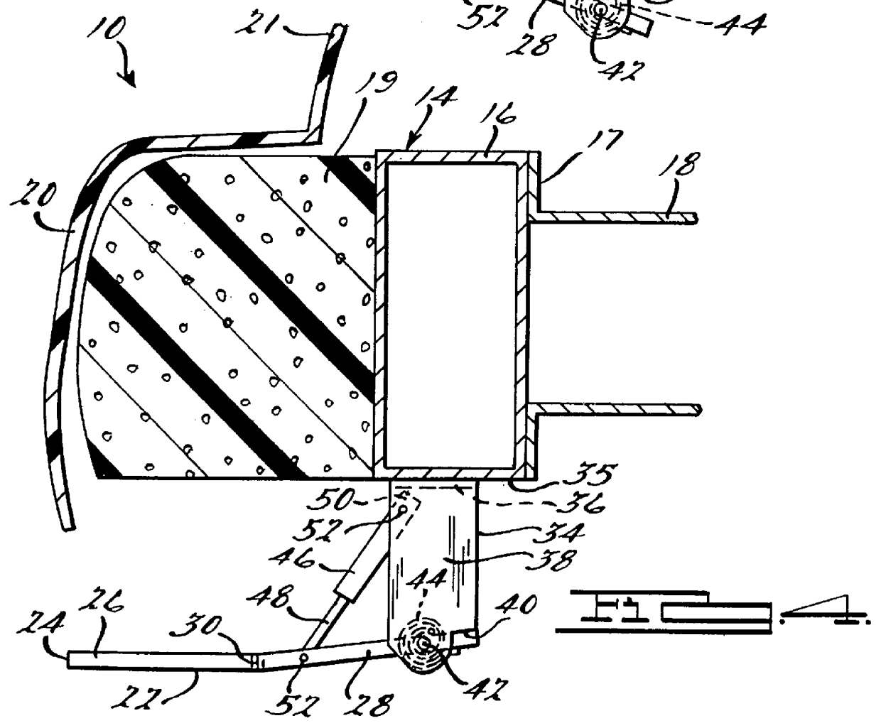
As illustrated in FIGS. 2 through 4, the bumper assembly 14 includes a bumper beam 16. The bumper beam 16 extends transversely and is secured to a forward end 17 of a pair of front rails 18 by suitable means such as welding. The bumper beam 16 is a hollow member having a generally rectangular shape. The bumper beam 16 is made of a relatively rigid material such as metal. The bumper system 14 includes a bumper 19. The bumper 19 extends transversely and is secured to the bumper beam 16 by suitable means such as fasteners (not shown). The bump...


PUM


Abstract

A stiffener assembly for a bumper system of a motor vehicle includes a stiffener operatively connected to the bumper system and movable between an up position and a down position based on a speed of the motor vehicle.

Description

1. Field of the InventionThe present invention relates generally to bumper systems for motor vehicles and, more specifically, to a stiffener assembly for a bumper system of a motor vehicle.2. Description of the Related ArtIt is known to provide a bumper system for a front end of a motor vehicle. Typically, the bumper system includes a bumper beam extending transversely and secured to a forward end of a pair of front rails which extend longitudinally and are spaced transversely. The bumper system also includes a bumper extending transversely and secured to the bumper beam. The bumper system may include a fascia disposed over and covering the bumper.Although the above bumper system has worked well, it suffers from the disadvantage that when a pedestrian impacts the bumper system, a lower leg of the pedestrian may bend under the motor vehicle. Therefore, there is a need in the art to provide a stiffener assembly for a bumper system of a motor vehicle.Accordingly, the present invention ...

Claims


Application Information

Patent Timeline
IPC IPC(8): B60R19/18B60R19/02B60R19/14B60R19/12B60R21/34
CPCB60R19/12B60R19/14B60R19/18B60R21/34
Inventor SCHUSTER, PETER JOHN
Owner FORD GLOBAL TECH LLC
Why Eureka
Try Eureka