Conductor stress relief apparatus

a stress relief apparatus and conductor technology, applied in mechanical apparatus, coupling device connection, rope/pulley cables, etc., can solve the problems of difficult to achieve, long installation time, and substantial tensile force on the conductor

Inactive Publication Date: 2000-09-26
LUCENT TECH INC
View PDF21 Cites 14 Cited by
  • Summary
  • Abstract
  • Description
  • Claims
  • Application Information

AI Technical Summary

Problems solved by technology

The combined weight of the cable can cause a substantial tensile force on the conductors.
This may be difficult to achieve with the above-listed stress relief devices.
Although the screw-mounted clamp member can satisfy a minimum pull out force requirement, it requires a tool, takes a relatively long time to install, and is liable to damage a cable if too much torque is applied to the screw.
It is more difficult to ensure that the minimum pull out force requirement is satisfied with the other three types of stress relief apparatus listed above.

Method used


Image

  • Conductor stress relief apparatus
  • Conductor stress relief apparatus
  • Conductor stress relief apparatus

Examples


Embodiment Construction

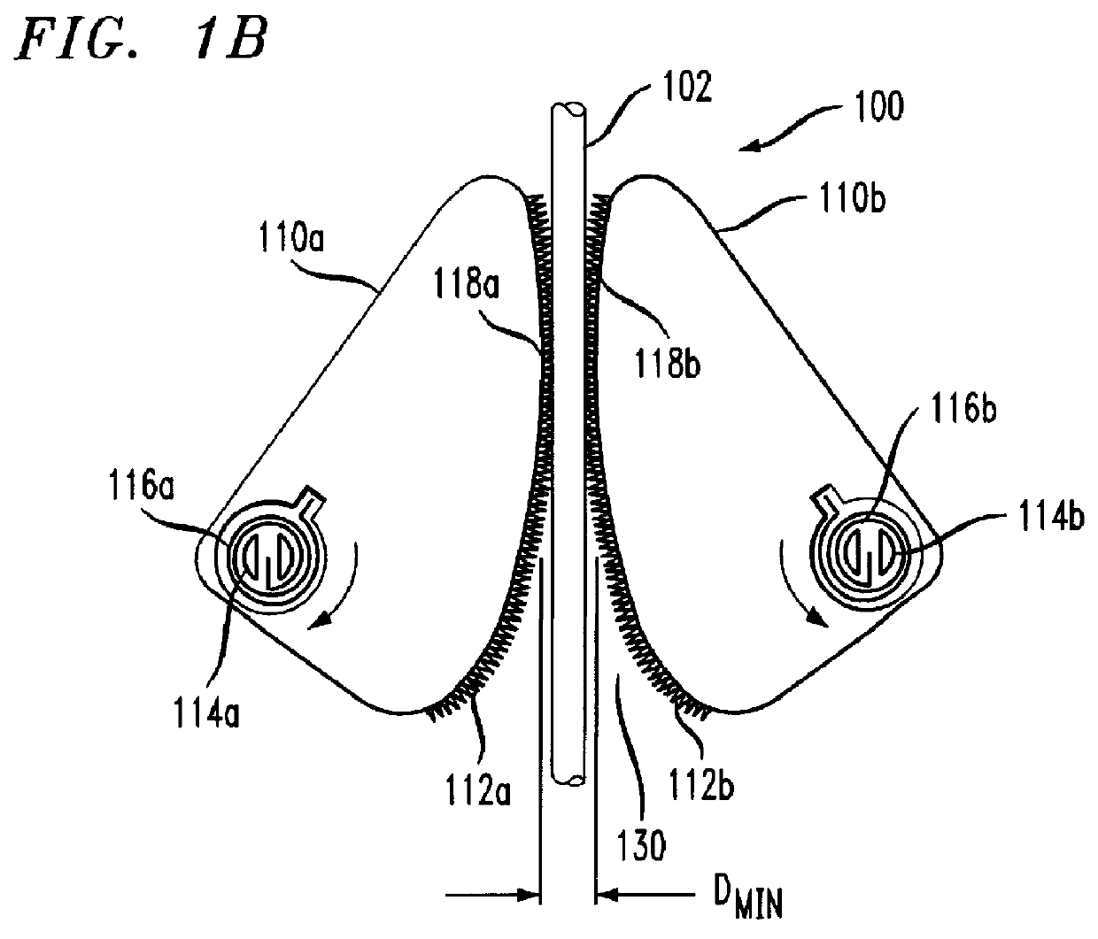
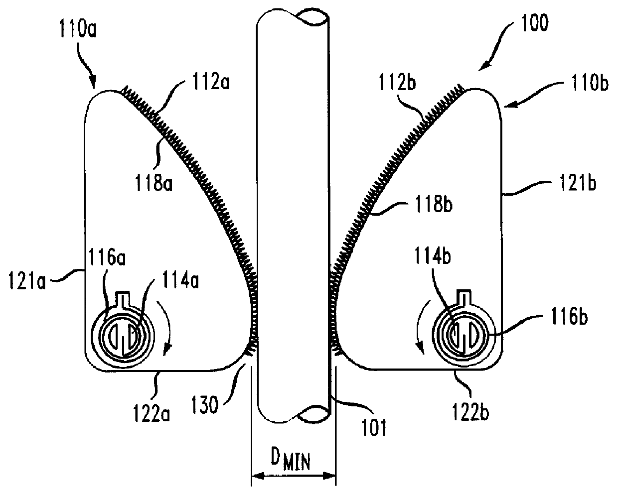
FIGS. 1A and 1B show a first exemplary embodiment of a stress relief apparatus 100 for a cable or conductor 101. The terms "cable" and "conductor" are used interchangeably below, because the apparatus is equally suitable for gripping a cable having plural conductors or gripping an individual conductor.

A first pivoting body 110a has a first contour 118a and a second pivoting body 110b has a second contour 118b. The contours 118a and 118b face each other, so that a smallest distance D.sub.min between the first and second contours 118a, 118b changes as the first body 110a pivots. An opposing means is provided by the second body 110b; the second body 110b pivots in the same way as the first body.

The first and second bodies 110a and 110b are pivotally mounted on first and second fixed-position studs 114a and 114b, respectively. In the example, each stud 114a and 114b is a split stud, for engaging an elastic member 116a and 116b, respectively. The first and second elastic members 116a and...


PUM


Abstract

A stress relief apparatus for a conductor has two bodies, at least one of which pivots so as to grip the conductor. The bodies have first and second contours, respectively. The contours face each other, so that the smallest distance between the first and second contours changes as the pivoting body pivots. First and second elastic members bias the first and second bodies, respectively, so that each of the first and second bodies engage a cable positioned between the first and second bodies. The bodies may both be pivoting bodies, and may be mirror images of one another. The contours of the bodies may have an elliptical shape. Alternatively, the bodies may have a circular shape, in which case each body pivots about a pivot point that is located at a non-zero distance from the center of that body.

Description

FIELD OF THE INVENTIONThe present invention is related to electrical and electronic systems generally, and more specifically to systems including cables and wires.DESCRIPTION OF THE RELATED ARTMany systems require a stress relief mechanism for cables and other conductors connected to those systems. It is common for a single cable to include as many as one hundred conductors. Without a stress relief mechanism, many conductors would be supported mainly by the connectors to which the ends of the conductors are attached. The combined weight of the cable can cause a substantial tensile force on the conductors. Stress relief mechanisms are often necessary to prevent the conductors from beingpulled out of their respective connectors by their own weight. Thus, many design specifications require that cables meet a minimum cable pull-out threshold.Common types of stress relief in the electrical arts include: (1) a clamp member that is attached to a housing or junction box by a screw or simila...

Claims


Application Information

Patent Timeline
Patent Type & Authority Patents(United States)
IPC IPC(8): H01R13/58H01R13/585
CPCH01R13/58H01R13/585Y10T24/3951
Inventor CRAFT, JR., THOMAS FRANCIS
Owner LUCENT TECH INC
Why Eureka
Try Eureka