Washer box

a technology for washing machines and washing tables, applied in the field of washing machines, can solve the problems of inconvenient access and operation of recessed valves, lack of knock-out test caps,

Inactive Publication Date: 2000-10-10
IPS
View PDF15 Cites 57 Cited by
  • Summary
  • Abstract
  • Description
  • Claims
  • Application Information

AI Technical Summary

Problems solved by technology

Other drawbacks include the lack of knock-out test caps at the drain connections to facilitate pressure

Method used


Image

  • Washer box
  • Washer box
  • Washer box

Examples


Embodiment Construction

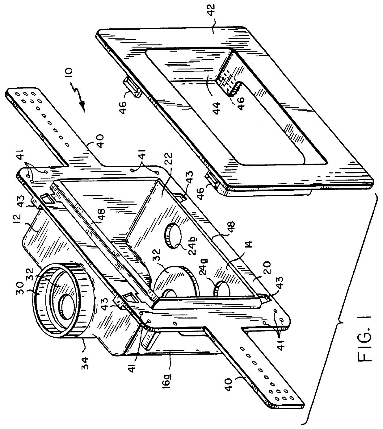
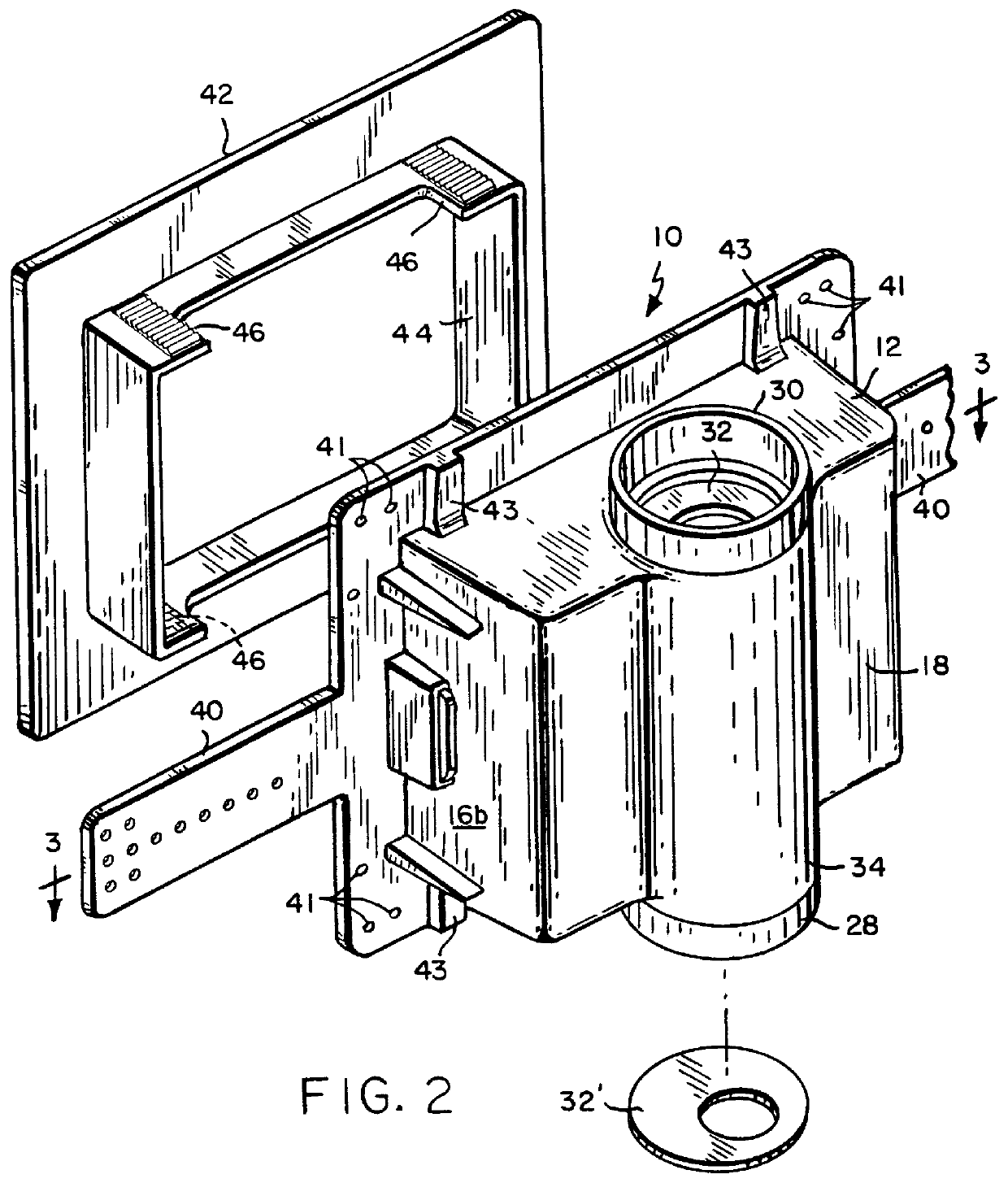
Referring initially to FIGS. 1-3, a washer box in accordance with the present invention is generally depicted at 10. The box comprises a hollow housing having a top wall 12, a bottom wall 14, side walls 16a, 16b, a back wall 18, and a front wall 20 defining a window 22 providing access to the housing interior.

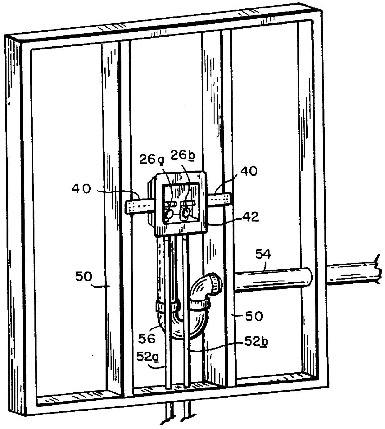
The bottom wall 14 has a pair of laterally spaced ports 24a, 24b aligned in a first plane P.sub.1 (shown in FIG. 3) parallel to and spaced rearwardly from the from front wall 20. It will be seen from FIG. 4 that the ports 24a, 24b are configured and arranged to accommodate hot and cold water shut off valves 26a, 26b.

A pair of coaxially aligned alternatively useable drains 28, 30 are provided in the bottom and top walls 14, 12. Each drain is closed and sealed by integrally formed knock-out caps 32, one being shown at 32' detached from the housing in FIG. 2. The drains 28, 30 are located rearwardly of the reference plane P.sub.1 and are contained in a second reference plane P.sub...


PUM


Abstract

A washer box has a hollow housing with top and bottom walls and a front wall defining a window providing access to the housing interior. A pair of laterally spaced ports in the bottom wall are aligned in a first reference plane parallel to and spaced rearwardly from the front wall, and are configured and arranged to accommodate the connection of hot and cold water supply lines to valves located within the housing. A pair coaxially aligned alternatively useable drain openings in the top and bottom walls are located rearwardly of the first reference plane in a second reference plane extending perpendicular to the first reference plane and bisecting the distance between the laterally spaced ports.

Description

1. Field of the InventionThis invention relates to an improvement in so-called "washer boxes" which provide hot and cold water supply and drain connection for washing machines.2. Description of the Prior ArtIn conventional washer boxes of the type described, for example, in U.S. Pat. Nos. 3,718,154 (Doumany); 3,847,175 (Anderson); 3,862,433 (Rousselet); 3,996,959 (Caruth); and 4,637,422 (Izzi), the position of the drain connections unduly limits the adaptability of the box to different hookup configurations. Other drawbacks include the lack of knock-out test caps at the drain connections to facilitate pressure testing of the drain lines, and inconveniently recessed valves which are difficult to access and operate.The present invention addresses these problems by providing an improved washer box configuration having top, bottom, front and rear wall, with hot and cold water supply ports located in the bottom wall and aligned in a common plane parallel to the front wall, and with coaxi...

Claims


Application Information

Patent Timeline
IPC IPC(8): E03C1/02D06F39/08
CPCE03C1/021D06F39/08Y10T137/698
Inventor HUMBER, JEFFREY A.
Owner IPS
Why Eureka
Try Eureka