Mechanism for constant balance

a constant balance and mechanism technology, applied in the direction of mechanical equipment, door/window protective devices, wing accessories, etc., can solve the problem that the copending application does not particularly address the tilt mechanism commonly associated with venetians

Inactive Publication Date: 2000-10-24
WEINREICH STEVE
View PDF16 Cites 29 Cited by
  • Summary
  • Abstract
  • Description
  • Claims
  • Application Information

AI Technical Summary

Problems solved by technology

The copending Application does not particularly address...

Method used


Image

  • Mechanism for constant balance
  • Mechanism for constant balance
  • Mechanism for constant balance

Examples


Embodiment Construction

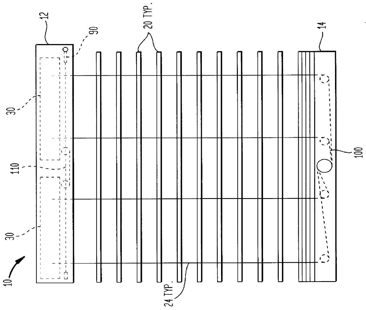
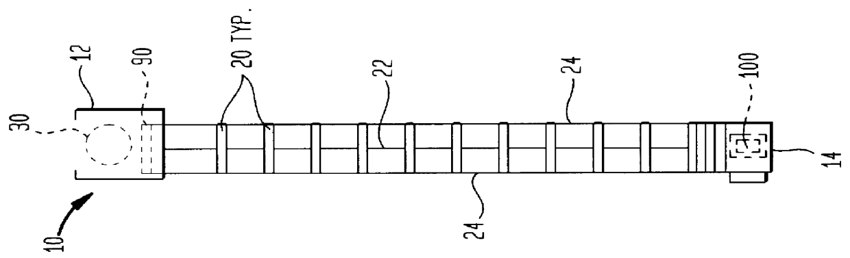
FIGS. 1 and 2 show ordinary venetian blind slats 20, with ladders (or tilt cords) 24 and lift cords 22, installed between the headrail 12 and bottom bar 14 of the invention 10.

The headrail 12 comprises two constant balance screw arrangements 30 to maintain the blind in balance as it is raised and lowered, a linkage 110 to assure their synchronization, and a compact tilter 90.

The bottom bar 14 comprises a balance adjusting assembly 100.

Operation of the Preferred Embodiment

Torque Transfer

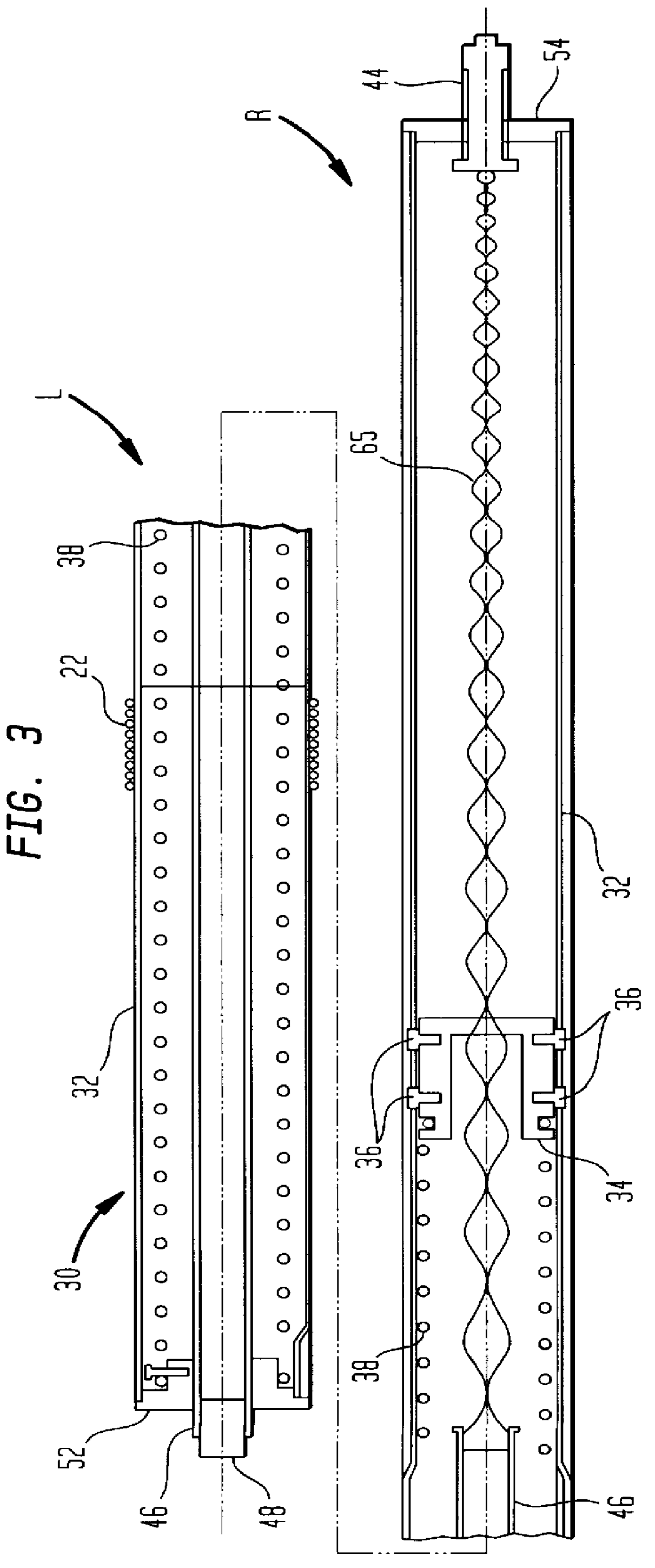
In preferred embodiments of the Invention of the copending Application, a common extension spring (or springs) urges a nut to translate along a screw. In practice, the screw is usually far shorter than the spring (when the spring is extended to working length) and is positioned near one end of the spring. According to the copending Application, the profile of the screw may be tapered.

In embodiments designed to lift loads that increase as they are lifted, the tapered profile will be smaller at that end...


PUM


Abstract

Constant balance of a varying load, particularly a window shade or blind, is maintained by providing a lifting force, preferably from a spring, through a mediating mechanism comprising a variable pitch screw assembly, such that the mechanical advantage of the mediating mechanism changes to allow the continuously decreasing spring force to apply an appropriate lifting force at all times. A variable pitch screw thread is formed as grooves in a cylindrical blank. The grooves are engaged by pins in a nut which thereby accomodates the variable pitch of the screw. A compact blind tilting mechanism is also incorporated. The capacity of the mechanism can be increased by linking several screw assemblies.

Description

This Invention is related to my patent application Ser. No. 08 / 794,872, MECHANISM FOR CONSTANT BALANCE, filed Feb. 5, 1997, now U.S. Pat. No. 6,003,584 which is incorporated herein by reference.BACKGROUND AND OUTLINE OF THE INVENTIONThe copending Application, MECHANISM FOR CONSTANT BALANCE, discloses a mechanism used to balance one force against another, where the ratio between the forces varies in a predictable way. The present Invention incorporates much of the teaching of the copending Application.It is known in the art to use springs to assist the raising of changing loads, particularly window shades and blinds. Michelman U.S. Pat. No. 2,350,286 has structural similarity to the present Invention, but does not track the changing load.Patents disclosing spring assists arranged to track the changing load include those using fusees (tapered sheaves) to mediate between spring and load, such as Cusumano, U.S. Pat. No. 2,420,301 and Hiller et al, U.S. Pat. No. 5,133,399. Kuhar, U.S. Pa...

Claims


Application Information

Patent Timeline
IPC IPC(8): E06B9/62E06B9/322E06B9/28E06B9/56E05F1/16
CPCE06B9/62E06B9/322
Inventor WEINREICH, STEVE
Owner WEINREICH STEVE
Why Eureka
Try Eureka