Wet gas processing method and the apparatus using the same

a technology of wet gas and processing method, which is applied in the direction of lighting and heating apparatus, separation process, emission prevention, etc., can solve the problems of inability to achieve smooth and consistent contact between liquid and gas flow, inability to design expensive equipment and equipment requirements, and inability to achieve smooth and consistent conta

Inactive Publication Date: 2000-10-31
MITSUBISHI HEAVY IND LTD
View PDF10 Cites 35 Cited by
  • Summary
  • Abstract
  • Description
  • Claims
  • Application Information

AI Technical Summary

Problems solved by technology

However, in a real situation a number of pumps would be used, posing a problem in terms of compactness as well as cost of equipment and operation.
We see, then, that this design is costly in terms of the equipment it requires.
However, with these prior art designs, the surface of the liquid in the liquid storage tank must be higher than the level from which the spray nozzles spray the liquid inside the absorption tower.
This makes it impossible to achieve smooth and consistent contact between the liquid and the gas flow.
The sulfur dioxide and particulate will not be effectively removed from the smoke, and the absorption liquid will not reach the top of the tower.
This will make it very difficult to return the absorption liquid to its tank, and the level in the tank will gradually decrease until finally it may happen that the liquid can no longer circulate under the force of its own weight.
As a result, the entire volume of the spray does not reach the mist eliminator in the top of the tower.
Instead it falls into the recovery vessel and accumulates there excessively.
These requirements were linked to a needless increase in the cost of the equipment.
This would be undesirable regardless of whether the gases were being released into the atmosphere or sent to a final stage processing apparatus.
This severely compromises the mist elimination function.
However, because some of the liquid generally drips to the bottom of the tower, it is not possible to collect 100% of the liquid using the collection unit only.
The abrupt compression and expansion of the exhaust gases in the space results in negative pressure, which causes minute droplets of the absorption liquid to rapidly disperse in the gas and become atomized.
If the absorption liquid removed from the recovery vessel and placed in the blowpit or other second tank is not recirculated to the first liquid storage tank, the system will not be able to function smoothly after that point.

Method used


Image

  • Wet gas processing method and the apparatus using the same
  • Wet gas processing method and the apparatus using the same
  • Wet gas processing method and the apparatus using the same

Examples


first embodiment

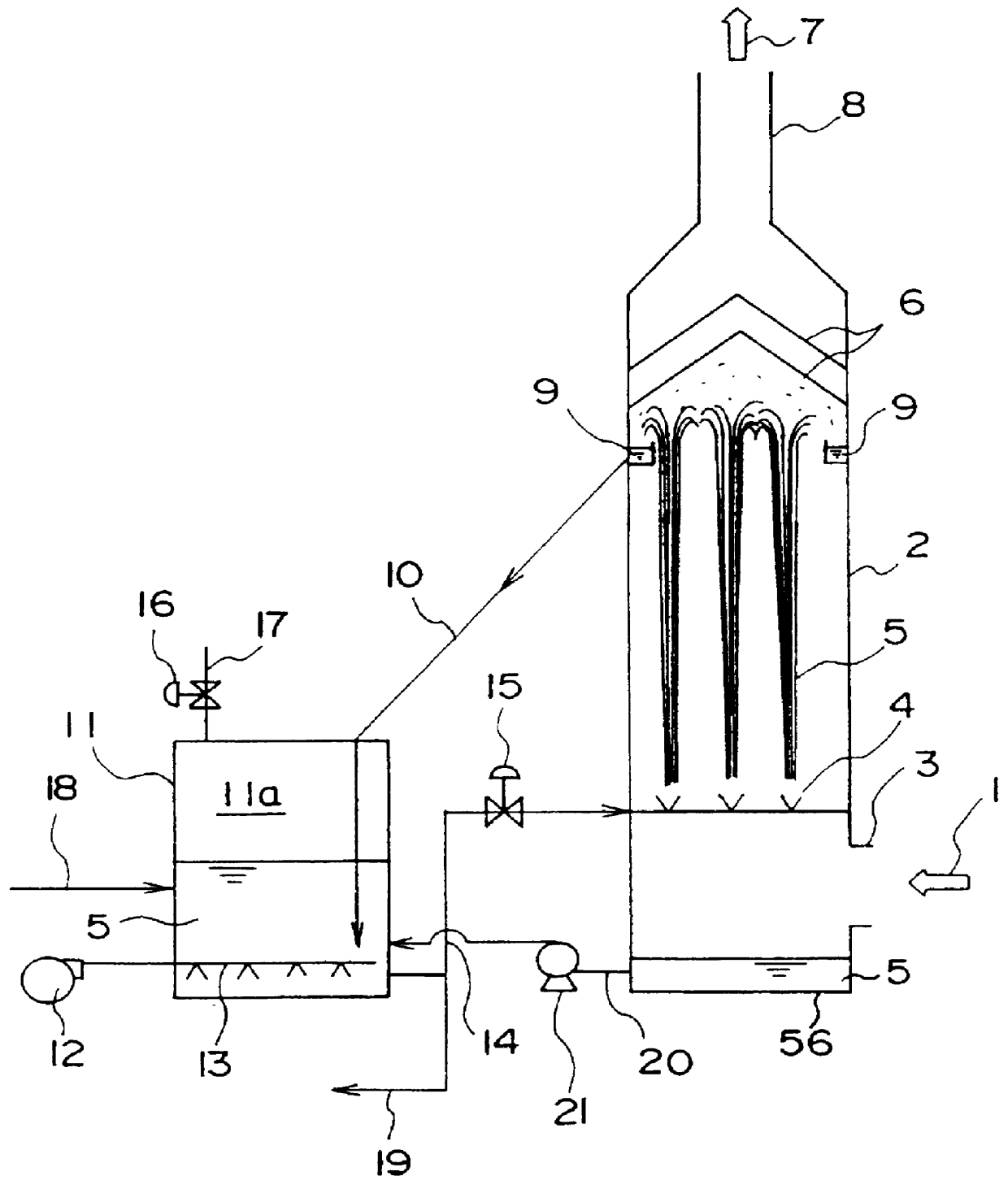
FIG. 1 is a rough sketch of a wet gas processing apparatus which is related to this invention.

In this figure, the exhaust gases 1 from the boiler or other combustion device are conducted into inlet 3 in the lower portion of absorption tower 2. The exhaust gases 1 which are conducted into the tower are brought in contact with the absorption liquid 5 supplied through spray nozzles 4 in the lower portion of the interior of the tower, and the targeted components of the gases are transferred from the gases to absorption liquid 5.

The fact that the targeted components of the gases can combine with the absorption liquid indicates that they are either soluble substances or particulate. In this embodiment, the targeted component is sulfur dioxide (SO.sub.2), which is soluble in an absorption liquid; and a slurry containing limestone, an absorbent, is used as the absorption liquid.

In this embodiment, the spray nozzles are upward-facing spray nozzles 4. When the absorption liquid 5 is sprayed u...

fourth embodiment

FIG. 14 concerns the fifth preferred embodiment of this invention, which successfully employs a prior art bypass 72 to enhance the effect achieved by the On main path 74, which links the boiler, combustor, or other source of exhaust gases with the smokestack or other means by which the gases are discharged to the atmosphere, there is a processing system in which the made to flow through absorption tower 2, where their velocity is used to entrain absorption liquid 5. The resulting liquid-vapor contact causes the targeted components of the gases to be absorbed by liquid 5. (A) shows which dampers are open and shut and which way the gases flow when the tower is started up. (B) shows the dampers and the gas flow when the exhaust gases from the boiler which are led into the tower have reached loading velocity.

As can be seen in FIG. 14, on main path 74, which links the boiler, combustor or other source of exhaust gases with the smokestack or other device to release the gases into the atm...

fifth embodiment

FIG. 15 shows an another modification of the fifth embodiment, in which panels are provided to control the width of the channel in absorption tower 2 through which the exhaust gases flow. A vertical panel 40 is provided in liquid-vapor contact zone 41. The panel 40 can move horizontally to change the cross sectional area of the passage traversed by the exhaust gases in contact zone 41.

FIG. 16 is yet another modification of the fifth preferred embodiment of this invention. It corresponds to FIG. 7, in which a number of panels control the width of the gas channel in absorption tower 2. Several panels are oriented vertically in liquid-vapor contact zone 41 with their bottom ends at different heights, step-fashion. By controlling the height of the liquid on the bottom of the tower, we can change the cross sectional area of the passage for the exhaust gases.

When the exhaust gases 1 conducted into the absorption tower 2 are flowing at a speed below the loading velocity of the tower, the p...


PUM

PropertyMeasurementUnit
flow velocityaaaaaaaaaa
velocityaaaaaaaaaa

Abstract

PCT No. PCT/JP98/05062 Sec. 371 Date Sep. 8, 1999 Sec. 102(e) Date Sep. 8, 1999 PCT Filed Nov. 10, 1998 PCT Pub. No. WO99/24148 PCT Pub. Date May 20, 1999This invention is related to a wet gas process which would not require a spray pump, and which would allow the absorption liquid to be recovered smoothly even if the flow velocity of the gases entrained to the liquid should decrease. A wet gas processing apparatus in which the absorption liquid collected in the first liquid storage tank is sprayed in a specified direction (which may be upward, horizontal or downward) by a discharge unit consisting of spray nozzles (14) or the like in the absorption tower. The sprayed liquid is brought into contact with the exhaust gases which are conducted into the tower, and the targeted components of the gases are absorbed and removed. This processing apparatus is distinguished by the following. The first liquid storage tank for the absorption liquid comprises a pressure tank (11) which generates a pressurized gas in the space above the surface of the collected liquid (11a). The increased pressure of the pressurized gas is employed to spray the liquid collected in the pressurized tank from the spray nozzle unit in the absorption tower. This apparatus is further distinguished as the following. This invention has overflow ports which generate a virtually horizontal overflow or source flow. The absorption liquid propelled by the overflow ports makes orthogonal contact with the flow of exhaust gases, which results in both atomization of the liquid and liquid-vapor contact.

Description

This invention concerns a wet gas processing method and apparatus to remove from exhaust gas certain targeted components such as those which are harmful. More specifically, it concerns a apparatus which brings about effective liquid-vapor contact between the absorption liquid and the exhaust gas resulting from combusting coal or heavy oil.TECHNICAL BACKGROUNDHeretofore, various types of liquid-gas contact apparatuses have been employed to remove sulfur dioxide from exhaust smoke using a wet-gas method. These would typically be used to remove harmful substances like sulfur dioxide from the exhaust smoke of a coal-burning boiler. One such apparatus, a previous design by the present petitioners which employs a liquid-column method, is described in Japanese Utility Patent Publication (Koukai) 59-53828.This apparatus has a number of spray nozzles arranged in an absorption tower. An absorption liquid such as lime slurry is sprayed upward from these spray nozzles to form an absorption colu...

Claims


Application Information

Patent Timeline
Patent Type & Authority Patents(United States)
IPC IPC(8): B01D53/80B01D53/18B01D53/78B01D53/14B01D53/50B01D47/06B01D53/34B01D53/77
CPCB01D53/1412B01D53/18B01D53/504B01D53/80B01D53/78F23J2219/40F23J2215/20
Inventor TAKASHINA, TORUKAMIYAMA, NAOYUKISHINODA, TAKEONAGAYASU, HIROMITSUOKINO, SUSUMUONIZUKA, MASAKAZUIWASHITA, KOICHIRONAKAMURA, SATOSHIINOUE, KENJI
Owner MITSUBISHI HEAVY IND LTD
Why Eureka
Try Eureka