Device for fast connection of a tube to a rigid element with anti-extraction ring and safety seal

a technology of anti-extraction ring and safety seal, which is applied in the direction of fluid pressure sealed joints, joints with sealing surfaces, sleeve/socket joints, etc., can solve the problem of not being able to push in the slide, and achieve the effect of improving the safety of coupling devices

Inactive Publication Date: 2000-11-14
LEGRIS
View PDF10 Cites 84 Cited by
  • Summary
  • Abstract
  • Description
  • Claims
  • Application Information

AI Technical Summary

Benefits of technology

The technical effect of this patent is to make safer coupling devices that can prevent accidents caused by someone accidentally pushing on a keeperspray mechanism.

Problems solved by technology

The technical problem addressed in this patent text needs to be identified by a senior R&D person who has read it through.

Method used


Image

  • Device for fast connection of a tube to a rigid element with anti-extraction ring and safety seal
  • Device for fast connection of a tube to a rigid element with anti-extraction ring and safety seal

Examples


Embodiment Construction

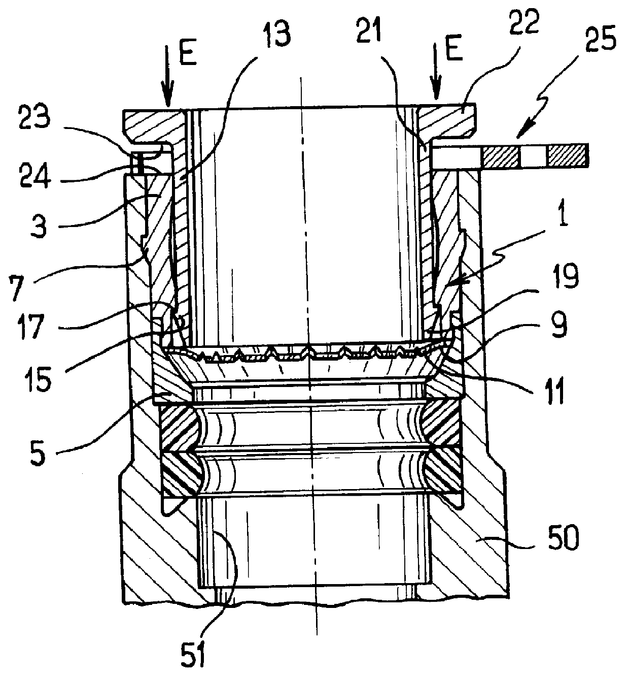
With reference to the figures, the quick-coupling device for coupling a tube to a rigid element 50 comprises a tubular insert 1 designed to be received in a bore 51 of the rigid element 50.

In this case, the insert 1 has two portions: a tubular body 3, and at the front of the body relative to the direction in which the insert 1 is inserted into the bore 51, a nose 5. The outside face of the body 3 is fitted with projections 7 in a Christmas tree shape for anchoring in the bore 51.

The body 3 and the nose 5 define between them a groove 9 which constitutes a housing for a washer 11 fitted with teeth for gripping and retaining the tube. The washer 11 is conventional, being elastically deformable and substantially frustoconical towards the front, i.e. towards the inside of the bore 51. Its inner circumference is of a diameter that is smaller than the diameter of the tube, thereby enabling it to "bite" into the tube and hold it against an extraction force.

A tubular declutching slide 13 is ...


PUM


Abstract

PCT No. PCT/FR98/02654 Sec. 371 Date Jun. 28, 1999 Sec. 102(e) Date Jun. 28, 1999 PCT Filed Dec. 8, 1998 PCT Pub. No. WO99/30071 PCT Pub. Date Jun. 17, 1999The invention relates to a quick-coupling device for coupling a tube to a rigid element (50) having a bore, the device comprising a tubular insert (1) having means (7) enabling it to be anchored in the bore of the rigid element (50), declutchable tube retaining means (11), and a slide (13) mounted to move in translation in the tubular insert (1) to declutch the retaining means (11) when it is pushed into the tubular insert (1). The declutching slide (13) possesses a rear portion which projects outside the tubular insert (1) and which presents a shoulder surface (23) situated facing an end surface (24) of the tubular insert (1) and co-operating with said end surface to define a groove in which a removable intermediate ring (25) is received to oppose pushing in of the declutching slide (13).

Description


Claims


Application Information

Patent Timeline
Owner LEGRIS
Why Eureka
Try Eureka