Multi-way input device

Inactive Publication Date: 2000-11-21
ALPS ALPINE CO LTD
View PDF8 Cites 19 Cited by
  • Summary
  • Abstract
  • Description
  • Claims
  • Application Information

AI Technical Summary

Benefits of technology

Further, since guide portions for guiding the pivot shaft portions to the engaging portions are formed in part of side walls of the second interlocking member which define the foregoing slot, the pivot shaft portions of the operating shaft can surely be guided to the engaging portions of the second interlocking member and the multi-way input device is superior in its assembling work efficiency.

Problems solved by technology

Besides, the work of inserting or press-fitting the round pin 46 into the second interlocking member 40 and caulking both ends thereof to prevent dislodgment is needed and therefore the assembling work for the conventional multi-way input device is so much complicated.

Method used


Image

  • Multi-way input device
  • Multi-way input device
  • Multi-way input device

Examples


Embodiment Construction

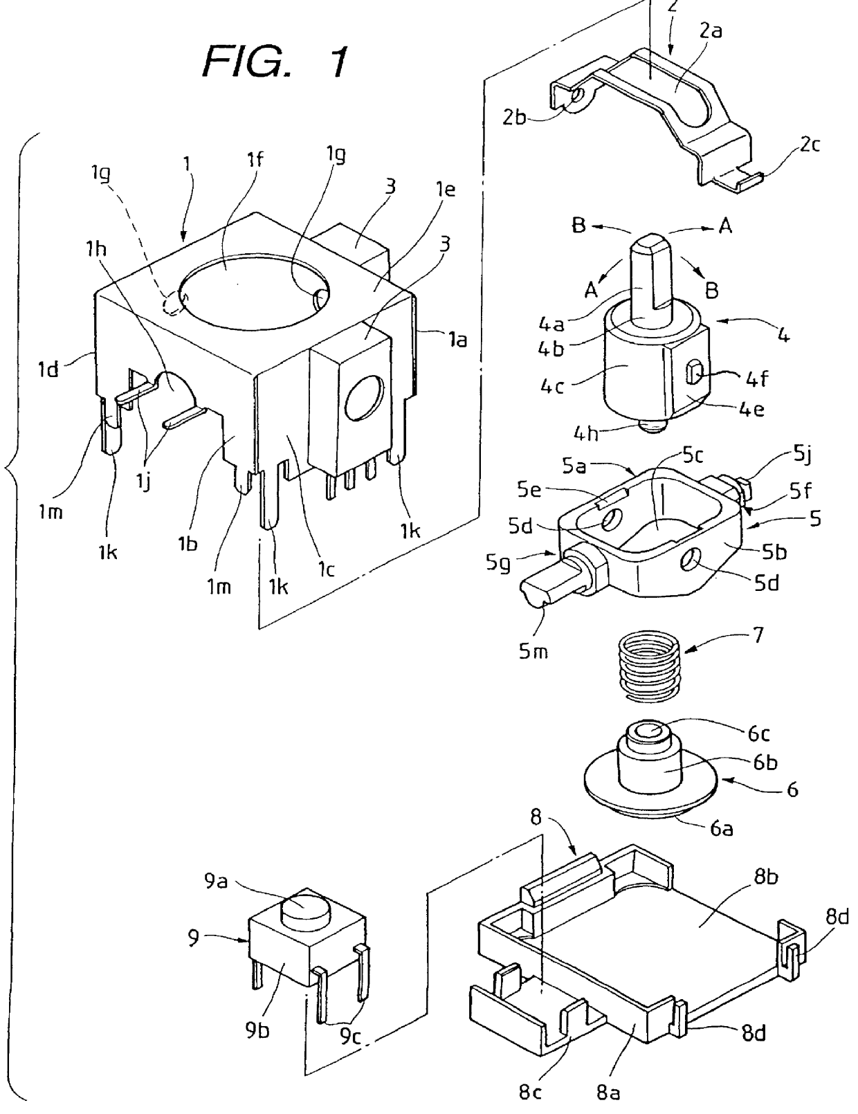
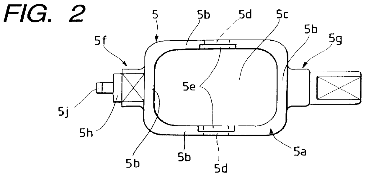
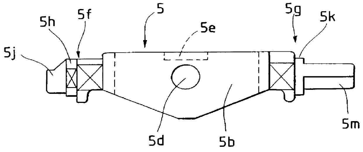
A multi-way input device according to an embodiment of the present invention will be described hereinunder with reference to FIGS. 1 to 10, of which FIG. 1 is an exploded perspective view of the multi-way input device, FIGS. 2 to 4 are diagrams illustrating a second interlocking member used in the multi-way input device, FIGS. 5 to 7 are diagrams illustrating an operating shaft used in the multi-way input device, and FIGS. 8 to 10 are diagrams illustrating the operation of the multi-way input device.

In the multi-way input device, as shown in FIG. 1, a frame 1 is disposed which is formed by an iron plate or the like. The frame 1 has side plates 1a, 1b, 1c and 1d formed by bending downward in the figure by means of a press or the like. The frame 1 has a hollow interior and its bottom is open. Its external form is generally in the shape of a rectangular parallelepiped. The top of the frame 1 is covered with a top plate 1e, with an operating hole 1f being formed centrally in the top pla...


PUM


Abstract

In the multi-way input device of the present invention, pivot shaft portions of an operating shaft and engaging portions of a second interlocking member are engaged with each other by snap-fitting to support the operating shaft in the second interlocking member. Thus, the operating shaft can be supported in the second interlocking member easily even by manual operation without requiring any special jig or the like.

Description

1. Field of the InventionThe present invention relates to a multi-way input device capable of operating a plurality of electric components at a time by operation of an operating shaft.2. Description of the Related ArtA conventional multi-way input device is constructed as in FIGS. 11 to 13, in which a first interlocking member 31 curved in an arch shape is disposed in the interior of a frame 30, the frame 30 being formed in the shape of a box having side plates and which is open on its lower side. The first interlocking member 31 has mounting portions 31a formed respectively at both ends thereof. The mounting portions 31a are fitted respectively into holes 30c and 30a formed in side plates of the frame 30, whereby the first interlocking member 31 is mounted rotatably in the interior of the frame 30.A hole 34 is formed in an end face of each mounting portion 31a and a rotary shaft 33 of a variable resistor 32 comes into engagement with the hole 34. Further, a slit 35 is formed longit...

Claims


Application Information

Patent Timeline
IPC IPC(8): G05G9/00G05G9/047H01C10/00H01C10/16G05G1/00G06F3/0338H01C10/20H01H13/70
CPCG05G9/047H01C10/16G05G2009/04777H01H13/70
Inventor SHIMOMURA, HISATO
Owner ALPS ALPINE CO LTD
Why Eureka
Try Eureka