Low current high temperature switch contacts

Inactive Publication Date: 2000-12-05
HONEYWELL INC
View PDF10 Cites 76 Cited by
  • Summary
  • Abstract
  • Description
  • Claims
  • Application Information

AI Technical Summary

Problems solved by technology

Mechanical switches for carrying low current at high temperature are often problematic.
High temperature prevents the use of certain plating materials, due to softening, and the low current does not provide sufficient energy, or spark, at the contacts to burn away contaminants that can

Method used


Image

  • Low current high temperature switch contacts
  • Low current high temperature switch contacts
  • Low current high temperature switch contacts

Examples


Embodiment Construction

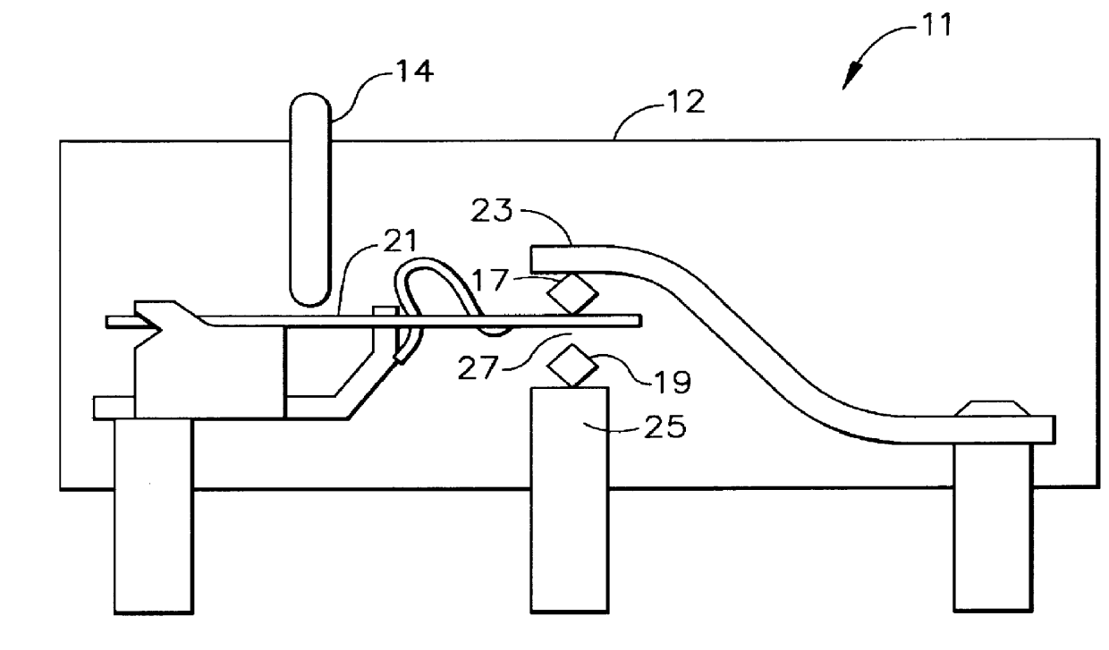
As seen in FIG. 2, a side view of a snap action switch is shown as a single pole double throw (SPDT) switch 11 with a case 12; plunger 14; a snap spring, common, moveable contact 21; and normally open 19 and normally closed 17 stationary contacts. According to the preferred embodiment, the stationary contacts 17, 19 of the SPDT switch 11 are bars of roughly square, or rectangular, cross section. The moveable contact 21 is a flat blade. While shown as one piece, the blade could be bifurcated. The stationary contacts 17, 19 are mounted on their posts 23, 25 respectively, by welding or other known attachment means, to present an edge, e.g. 27 to the moveable contact 21. The edge 27 concentrates the force of the moveable contact 21 along a single line 29 (FIG. 3) to provide good wiping action to scrub away contaminants and / or particulates when the moveable contact meets the stationary contacts. The line of contact 29 further provides a sufficient area of contact for electrical connectio...


PUM


Abstract

A low ampere mechanical switch has a contact design creating a line of contact between the moveable and stationary contacts. The stationary contacts are stainless steel and the moveable contact is Inconel TM . Both contacts have a thin plating of gold alloy to provide for good mechanical strength at high temperature with a natural lubricating ability. The contact physical design provides good wiping action and mechanical contact while preventing troughing.

Description

1. Field of the InventionThe invention relates generally to low ampere-high temperature switches. The invention relates more specifically to the contact designs for such switches.2. Description of Prior ArtMechanical switches for carrying low current at high temperature are often problematic. Low current is generally meant to include the range of 0.001 to 0.050 amp. High temperature is generally meant to include 500.degree. F.-900.degree. F. High temperature prevents the use of certain plating materials, due to softening, and the low current does not provide sufficient energy, or spark, at the contacts to burn away contaminants that can occur on all contact materials except the most noble materials.Because many plating materials become soft at high temperatures, troughing of the contact point, wherein a groove is formed in the mating surfaces as seen in FIG. 1, may occur on the softer of the contact surfaces, typically the moveable contact which is often plated with a thicker layer ...

Claims


Application Information

Patent Timeline
IPC IPC(8): H01H1/06H01H1/02H01H1/04
CPCH01H1/06H01H1/04
Inventor DAWSON, ARTHUR WAYNE
Owner HONEYWELL INC
Why Eureka
Try Eureka