Strip casting apparatus

Inactive Publication Date: 2001-01-02
CASTRIP
View PDF5 Cites 33 Cited by
  • Summary
  • Abstract
  • Description
  • Claims
  • Application Information

AI Technical Summary

Problems solved by technology

The setting up and adjustment of the casting rolls in a twin roll caster is a significant problem.
Previously proposed arrangements have employed roll mounting and biasing means in which require relative sliding mo

Method used


Image

  • Strip casting apparatus
  • Strip casting apparatus
  • Strip casting apparatus

Examples


Embodiment Construction

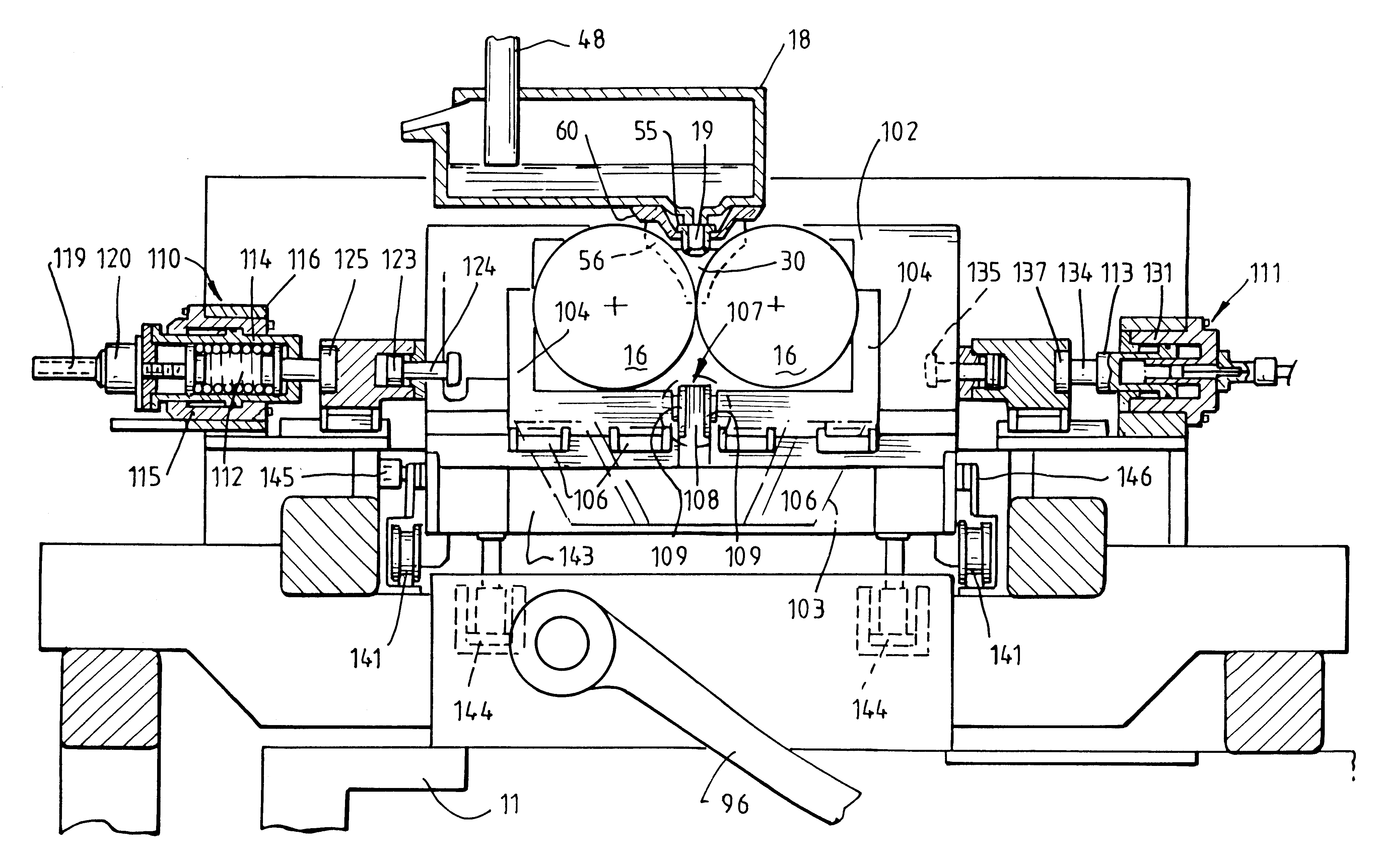
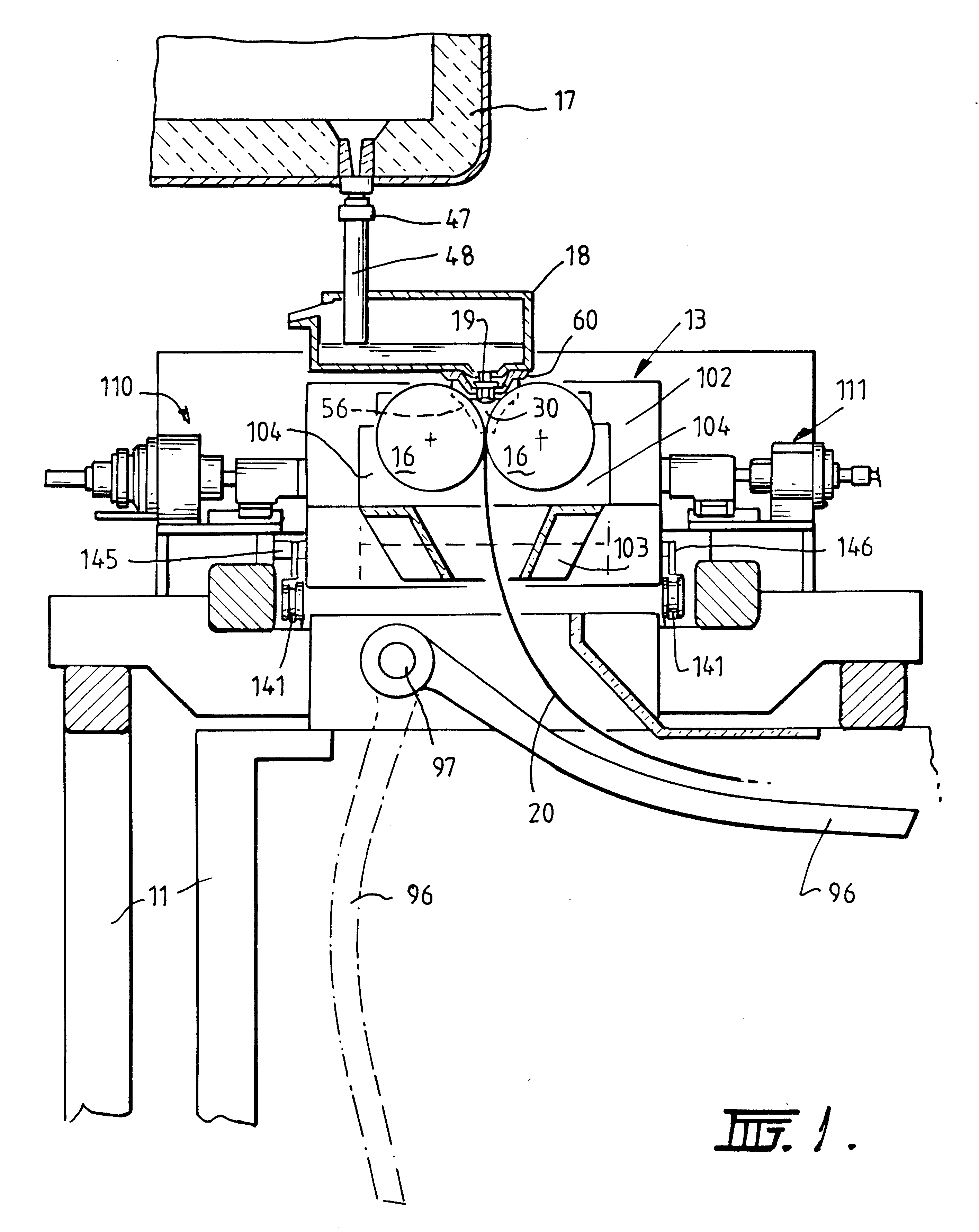
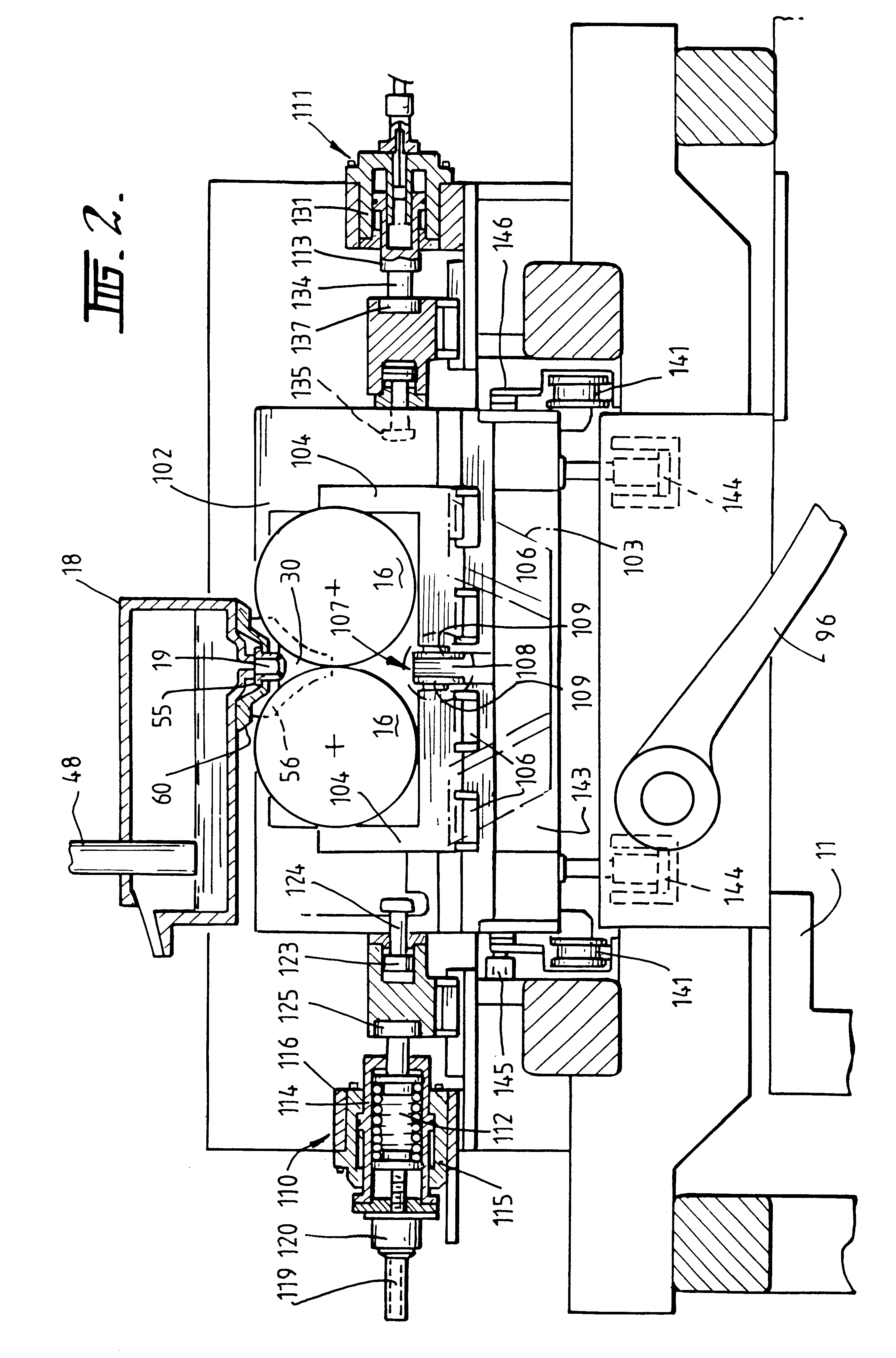
The illustrated caster comprises a main machine frame 11 which stands up from the factory floor (not shown) and supports a casting roll module in the form of a cassette 13 which can be moved into an operative position in the caster as a unit but can readily be removed when the rolls are to be replaced. Cassette 13 carries a pair of parallel casting rolls 16 to which molten metal is supplied during a casting operation from a ladle (not shown) via a tundish 17, distributor 18 and delivery nozzle 19 to create a casting pool 30. Casting rolls 16 are water cooled so that shells solidify on the moving roll surfaces and are brought together at the nip between them to produce a solidified strip product 20 at the roll outlet. This product may be fed to a standard coiler.

Casting rolls 16 are contra-rotated through drive shafts 41 from an electric motor and transmission mounted on the main machine frame. The drive shaft can be disconnected from the transmission when the cassette is to be remov...


PUM

PropertyMeasurementUnit
Forceaaaaaaaaaa
Widthaaaaaaaaaa

Abstract

Twin roll caster for continuously casting metal strip comprises a pair of parallel casting rolls (16) to which molten metal is supplied through a delivery nozzle (19). The rolls are mounted on roll carriers (104) moveable on a frame (102) to allow rolls (16) to move toward and away from one another. Biasing units (110, 111) allow inward biasing forces to be applied to the roll carriers (104) so as to bias one of the rolls (104) toward the other. The biasing units (110) incorporate biasing springs and means to adjust the thrust exerted by the springs.

Description

1. Field of the InventionThis invention relates to the casting of metal strip. It has particular application to the casting of metal strip by continuous casting in a twin roll caster.2. Description of Related ArtIn a twin roll caster molten metal is introduced between a pair of contra-rotated horizontal casting rolls which are cooled so that metal shells solidify on the moving roll surfaces and are brought together at the nip between them to produce a solidified strip product delivered downwardly from the nip between the rolls. The term "nip" is used herein to refer to the general region at which the rolls are closest together. The molten metal may be poured from a ladle into a smaller vessel or series of smaller vessels from which it flows through a metal delivery nozzle located above the nip so as to direct it into the nip between the rolls, so forming a casting pool of molten metal supported on the casting surfaces of the rolls immediately above the nip and extending along the le...

Claims


Application Information

Patent Timeline
IPC IPC(8): B22D11/06
CPCB22D11/0622B22D11/0682B22D41/24
Inventor FISH, JOHN ANDREWKATO, HEIJI
Owner CASTRIP
Why Eureka
Try Eureka