Magnetically journalled rotational arrangement

a rotational arrangement and magnetic journal technology, applied in the field of magnetic journalled rotational arrangement, can solve the problems of considerable mechanical journalled rotational arrangemen

Inactive Publication Date: 2001-01-30
TC1 LLC
View PDF13 Cites 50 Cited by
  • Summary
  • Abstract
  • Description
  • Claims
  • Application Information

AI Technical Summary

Problems solved by technology

Magnetically journalled rotational arrangements are used today in numerous fields of application, in particular, however, where mechanically journalled rotational arrangements have considerable disadvantages, thus e.g. in stirrers or forwarding apparatuses for highly pure or biological liquids such as, for example, blood.

Method used


Image

  • Magnetically journalled rotational arrangement
  • Magnetically journalled rotational arrangement
  • Magnetically journalled rotational arrangement

Examples


Embodiment Construction

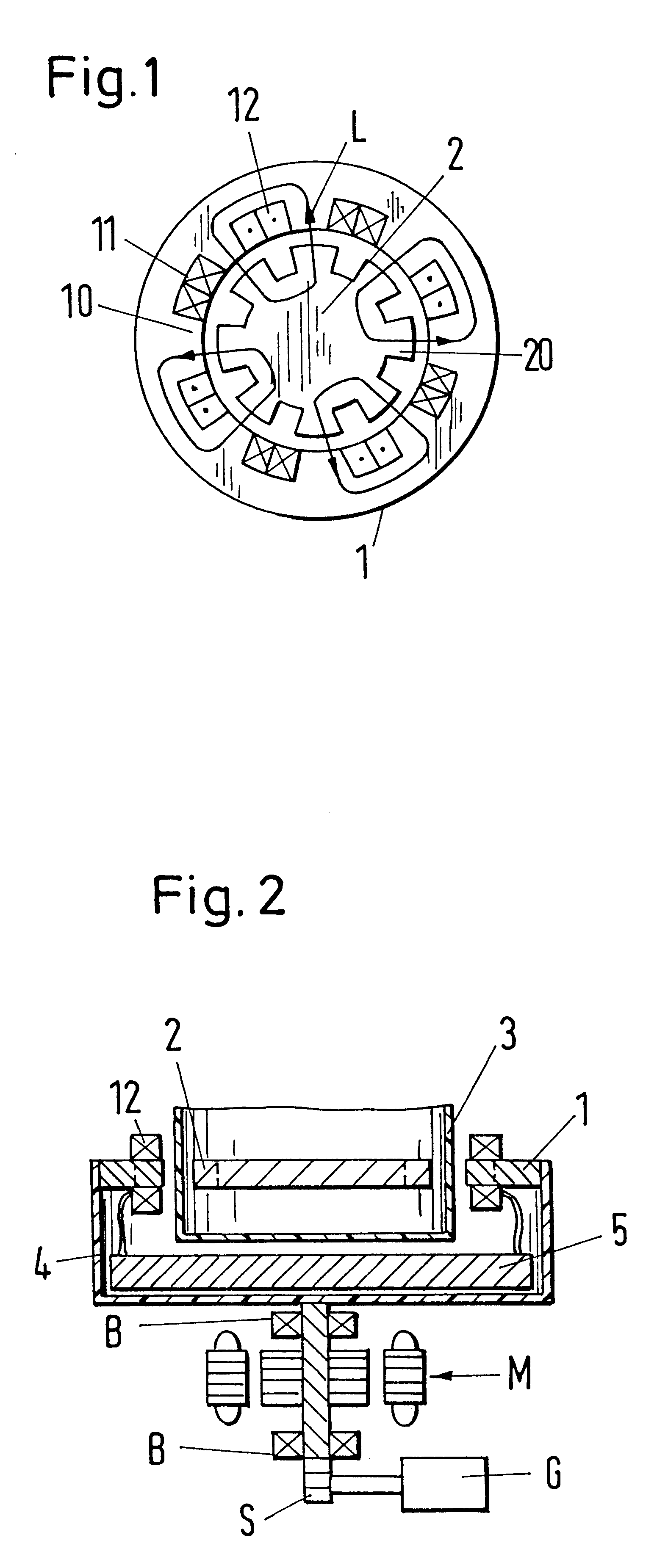
In the sketch of the principle of an exemplary embodiment of the rotational arrangement (here, a radial magnetic bearing) in accordance with the invention illustrated in FIG. 1, one recognizes a bearing stator 1 and a rotor 2. The bearing stator 1 has teeth 10 and the rotor 2 has corresponding teeth 20, with the teeth 10 and 20 of the bearing stator 1 and of the rotor 2 being arranged to point in the direction of one another. The number of the teeth 10 of the bearing stator 1 and of the teeth 20 of the rotor 2 are in agreement. Grooves 11 are located between the teeth 10 of the bearing stator 1; corresponding grooves 21 are located between the teeth 20 of the rotor 2. Windings 12 are wound around the individual teeth 10 of the bearing stator 1. During operation, these windings are flowed through by currents e.g. in the illustrated manner, so that the magnetic circuits indicated by the arrows L are formed. For the sake of better clarity, only a few of these magnetic circuits are repr...


PUM


Abstract

A magnetically journalled rotational arrangement comprises a bearing stator and a rotor, with the bearing stator being magnetically coupled to the rotor and producing a magnetic journalling of the rotor. The bearing stator is rotatably journalled. Furthermore, a rotary drive which is associated with the bearing stator is provided, with a rotation of the bearing stator producing a rotation of the rotor via the magnetic coupling of the stator to the rotor.

Description

1. Field Of The InventionThe invention relates to a magnetically journalled rotational arrangement. The invention also relates to forwarding apparatuses, carrier apparatuses, blowers and stirrers with a rotational arrangement of this kind.2. Description Of The Prior ArtMagnetically journalled rotational arrangements are used today in numerous fields of application, in particular, however, where mechanically journalled rotational arrangements have considerable disadvantages, thus e.g. in stirrers or forwarding apparatuses for highly pure or biological liquids such as, for example, blood. Magnetically journalled rotational arrangements are also used in applications such as clean room blowers where high demands are placed on cleanliness and no contamination, such as is caused e.g. by gases which can escape from the lubricants of mechanical bearings, may be tolerated. In these applications, both a journalling of the rotor (which can be designed e.g. as the vaned wheel of a pump) and a r...

Claims


Application Information

Patent Timeline
Patent Type & Authority Patents(United States)
IPC IPC(8): H02K49/06H02K49/00A61M1/10H02K7/09A61M60/113A61M60/232A61M60/422A61M60/538A61M60/546A61M60/822A61M60/849
CPCF16C32/0493H02K49/06A61M1/1015A61M1/1036H02K7/09F16C2380/26F16C2316/18A61M60/422A61M60/419A61M60/546A61M60/113A61M60/232A61M60/538A61M60/822A61M60/849
Inventor SCHOB, RETO
Owner TC1 LLC
Why Eureka
Try Eureka