Method and apparatus for compressing gaseous fuel in a turbine engine

a turbine engine and gaseous fuel technology, applied in the direction of turbine/propulsion engine ignition, engine starter, machine/engine, etc., can solve the problems of high cost of known gas compressors and significant energy consumption

Inactive Publication Date: 2001-02-27
CAPSTONE TURBINE
View PDF16 Cites 26 Cited by
  • Summary
  • Abstract
  • Description
  • Claims
  • Application Information

AI Technical Summary

Benefits of technology

Accordingly, an object of the present invention is to provide a method and apparatus for compressing ga

Problems solved by technology

A major problem with the use of natural gas is that it must be compressed enough to enter the

Method used


Image

  • Method and apparatus for compressing gaseous fuel in a turbine engine
  • Method and apparatus for compressing gaseous fuel in a turbine engine
  • Method and apparatus for compressing gaseous fuel in a turbine engine

Examples


Embodiment Construction

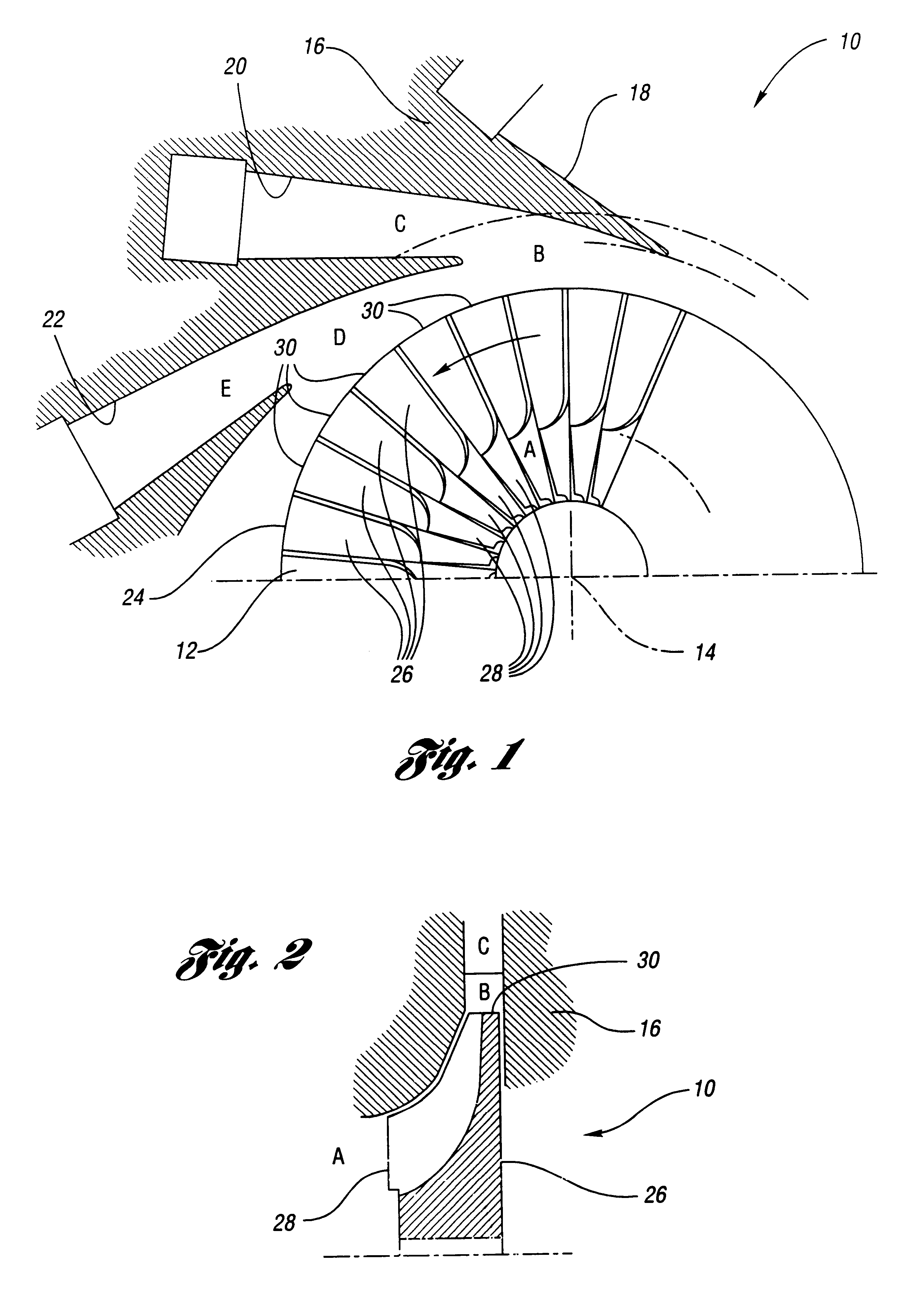
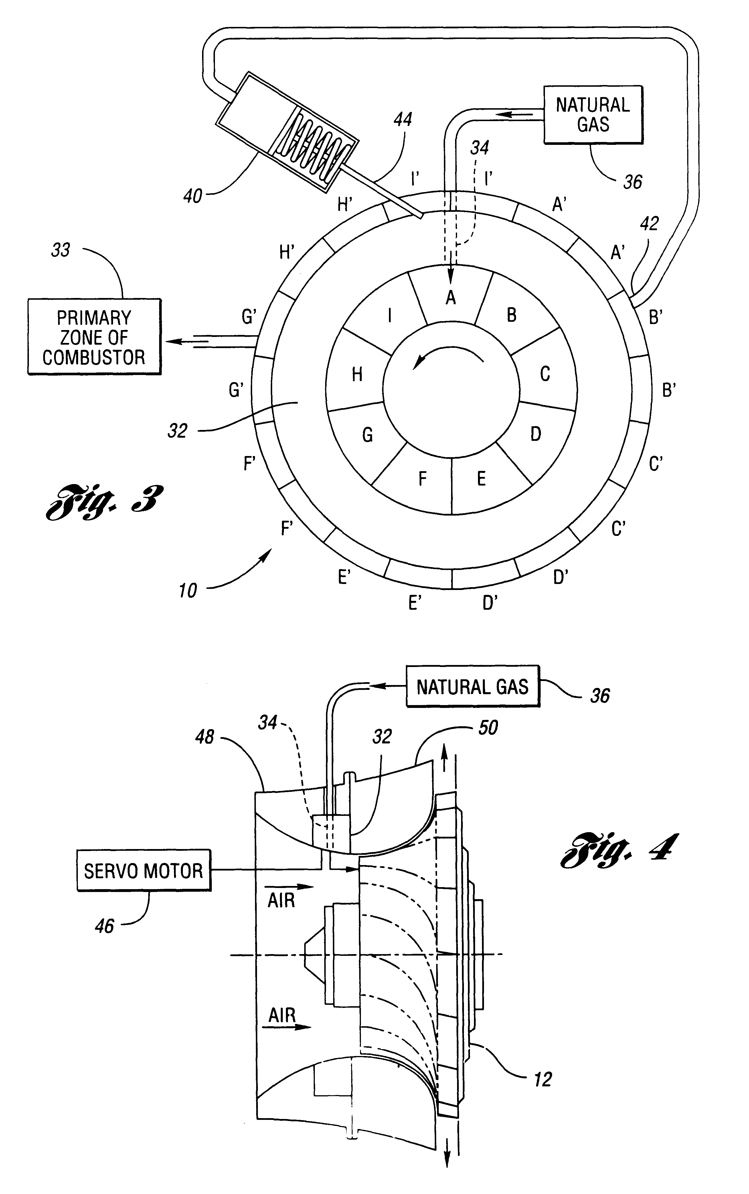
Referring to FIGS. 1 and 2, a compressor 10 is shown for use with the present invention. The compressor 10 includes an impeller 12 which is rotatable about an impeller axis 14, and a compressor body 16 which forms a plurality of diffuser channels 18, 20, 22 spaced apart radially beyond the periphery 24 of the impeller 12.

The impeller 12 includes a plurality of impeller vanes 26, each of which includes inlet and outlet ends 28,30, respectively.

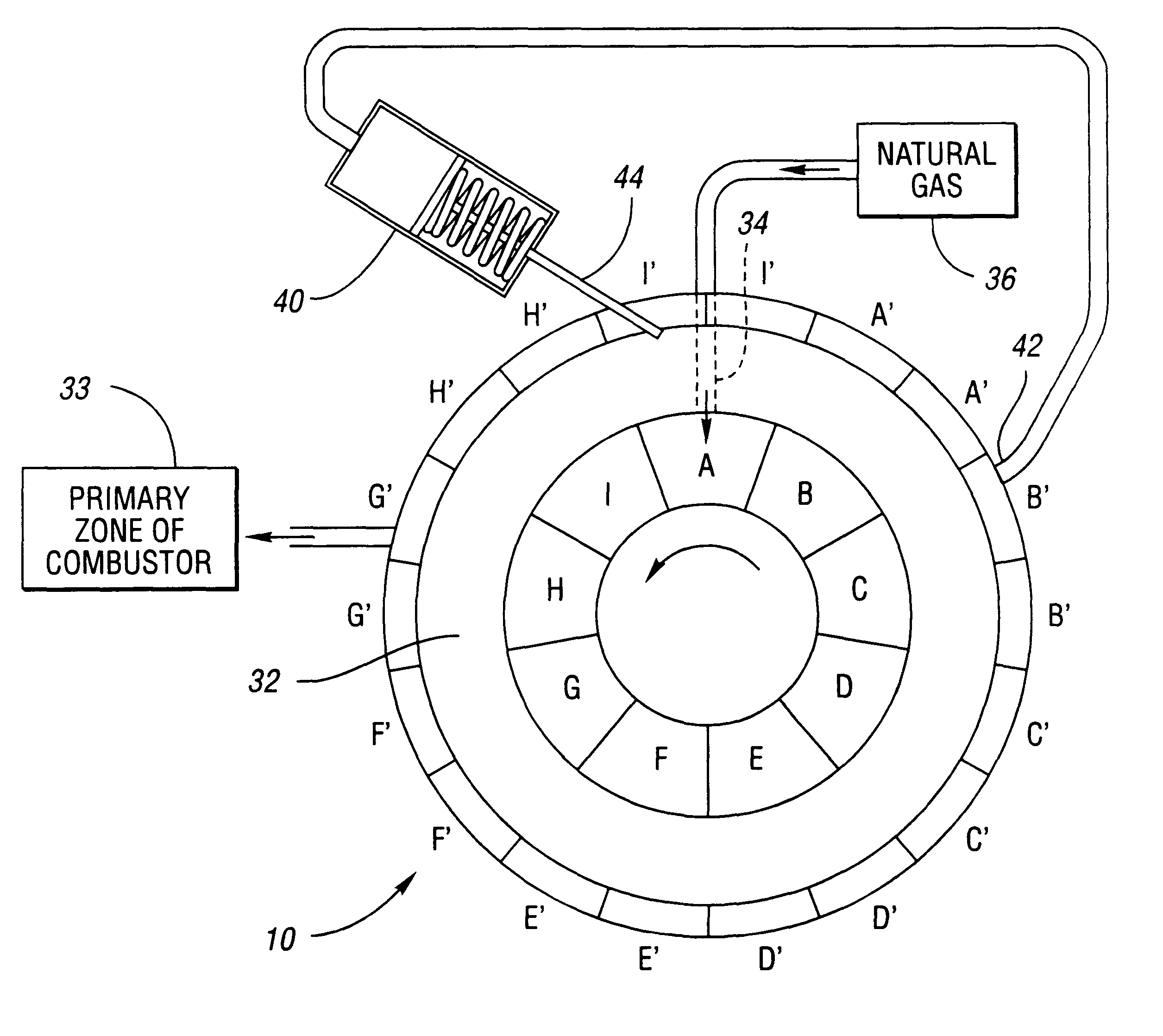
If the impeller 12 were not turning but still had air flowing through it, the air entering at point A would discharge at point B and enter diffuser channel C. However, the impeller 12 would be rotating in operation, and as it turns slowly the exit compressor discharge will be at point D and the air will enter diffuser channel E (reference number 22). As it turns faster, the diffuser channel through which the air enters will move further around. At any given speed and temperature, all of the air entering the compressor at point A will go into on...


PUM


Abstract

A gas turbine engine includes a rotatable impeller having a plurality of vanes with inlet and outlet ends. A plurality of diffuser channels are spaced apart radially beyond the outlet ends. A movable source of gaseous fuel is positioned adjacent the inlet ends of the vanes. The movable source of gaseous fuel is movable as a function of the rotational speed of the impeller, whereby the flow of gaseous fuel injected from the movable source is ejected from the outlet ends of the vanes into a selected one of the plurality of diffuser channels to facilitate combustion.

Description

The present invention relates to a method and apparatus for compressing gaseous fuel in the rotatable impeller of a gas turbine engine.A typical gas turbine engine includes a power section, a gear box, and various accessories such as a starter, fuel control, etc. The power section includes a compressor, a turbine, and a combustor. The compressor and turbine sections of the engine can rotate at speeds as high as 100,000 rpms. Air is compressed in the compressor to several atmospheres, for example, before it goes to the combustor. The combustor is split into two zones. At full load, the primary combustion chamber operates at fairly close to stoichiometric, the ideal fuel / air ratio. All of the fuel, and approximately 1 / 4 of the air or less, start to burn in this zone. The remainder of the air enters the secondary combustion zone through holes in the burner liner. This air provides a relatively cool blanket between the burning gases and the liner before it mixes. This serves to keep the...

Claims


Application Information

Patent Timeline
IPC IPC(8): F02C3/22F02C7/22F02C7/236F02C3/20
CPCF02C3/22F02C7/2365
Inventor MACKAY, ROBIN
Owner CAPSTONE TURBINE
Why Eureka
Try Eureka