Portable extraction cleaner

a cleaner and portable technology, applied in the field of extraction cleaners, can solve the problems of unfavorable home environment, inability to make these cleaners in many different colors, and the storage of hoses and electrical cords when the cleaner is not in use, so as to reduce the noise in the surrounding area

Active Publication Date: 2006-07-11
BISSELL INC
View PDF20 Cites 153 Cited by
  • Summary
  • Abstract
  • Description
  • Claims
  • Application Information

AI Technical Summary

Benefits of technology

[0013]In one embodiment, clean air exhaust vents are provided on a side of the housing base and are connected to an impeller outlet opening for exhausting air from the housing enclosure. The suction motor and impeller assembly are part of a sealed clean air extraction system that reduces noise to the surrounding area due to the isolation of the suction motor and impeller assembly and the positioning of exhaust vents on the underside of the extraction cleaner.

Problems solved by technology

The storage of the hose and the electrical cord when the cleaner is not in use has always presented a problem.
Due to the limitation of shelf space and inventory control, it has not been thought to make these cleaners in many different colors.
Further, the small footprint and portability of these machines have presented challenges in packaging the separate solution and recovery tanks in a way for easy removal and replacement of the tanks in the canister housing.
In addition, maintaining a proper weight balance for carrying these small cleaners has also been a challenge, especially in view of the varying amounts of liquid that may be present in the solution and recovery tanks during use of the cleaners.
In addition, the small package coupled with high efficiency motors and impellers result in undesirable noise in the home environment.

Method used


Image

  • Portable extraction cleaner
  • Portable extraction cleaner
  • Portable extraction cleaner

Examples


Embodiment Construction

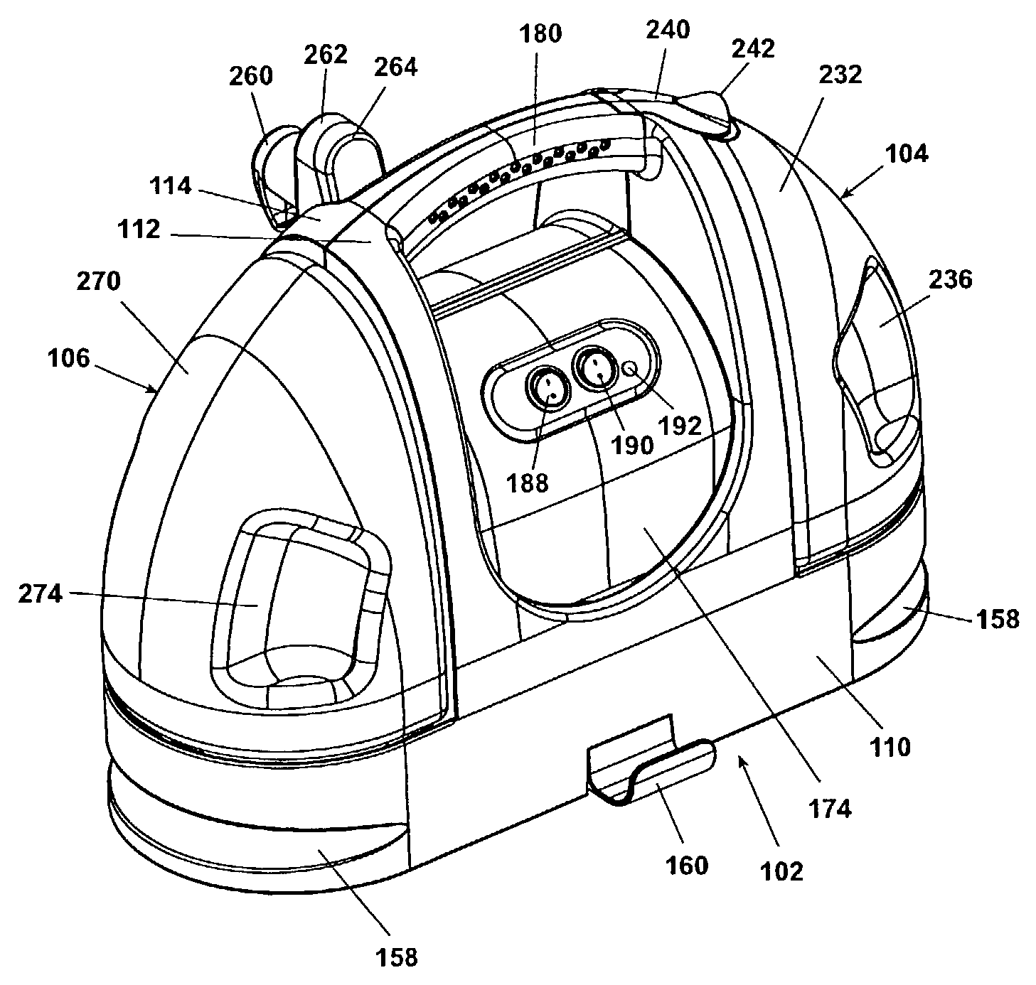
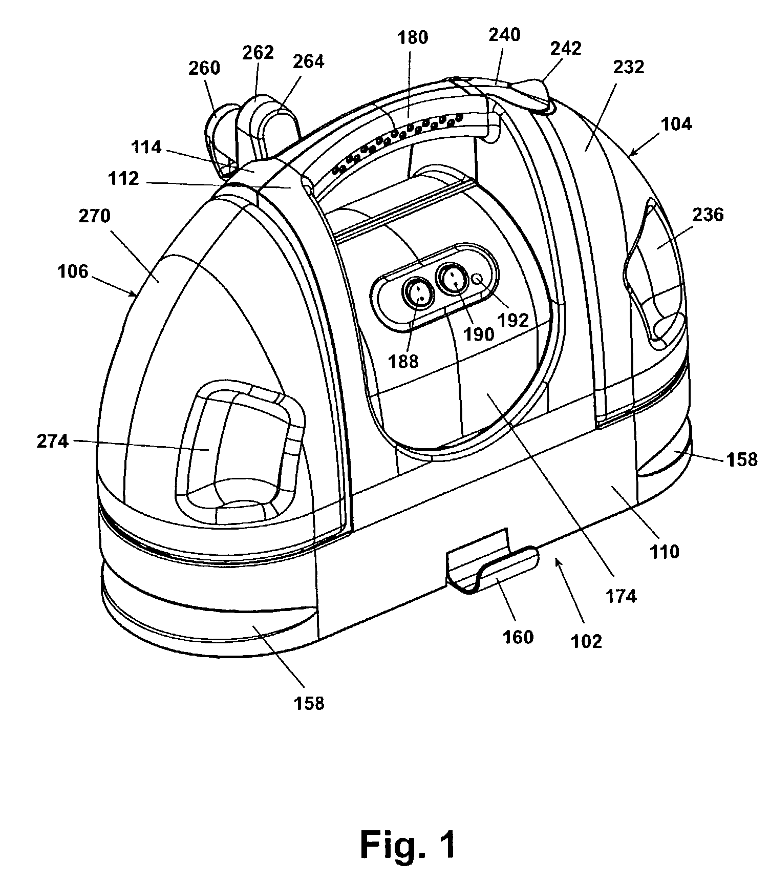
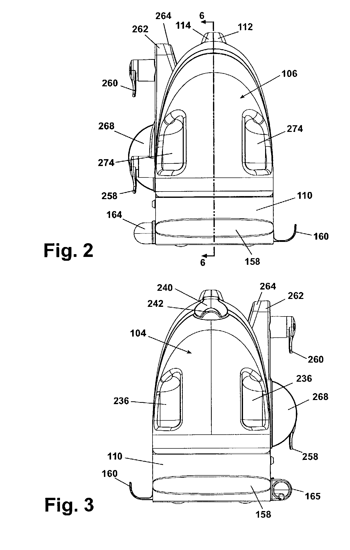
[0028]Referring to FIGS. 1–5, a portable extraction cleaner according to the invention comprises a main housing assembly 102, a recovery tank assembly 104 and a clean solution tank assembly 106. The main housing assembly 102 comprises a housing base 110 and first and second shell halves 112, 114. The recovery tank assembly 104 is principally contained within a recovery tank 232 having integrally molded handgrip indentations 236. In a preferred embodiment, main housing assembly 102 is formed of an opaque material, but can be formed of a translucent or transparent material. The recovery tank 232 can be formed of a transparent or tinted translucent material for user viewing of the contents of the tanks.

[0029]The housing base 110 is defined about its perimeter by a skirt 150 having a hose clip receiving recess 162 on the front face thereof and a flexible suction hose recess 1158 on each end thereof. The hose clip receiving recess 162 is adapted to receive a flexible suction hose clip 16...


PUM


Abstract

A portable extraction cleaning machine has a housing assembly including a housing enclosure centrally mounted on a housing base and a handle adapted for user carrying of the extraction cleaner, a suction motor and impeller assembly sealed within the housing enclosure and a solution tank for cleaning solution and a recovery tank removably mounted to the housing base in a fore and aft position. The recovery tank has an integrally molded spout and an air/liquid separator comprising a riser tube having an internal divider separating the riser tube into fluidly isolated first and second conduits. A plurality of different decorative face plates are adapted to be removably mounted to the housing enclosure and each of which is adapted to cover at least a substantial visible portion of the visible surface of the housing enclosure when mounted on the housing enclosure.

Description

CROSS REFERENCE TO RELATED APPLICATIONS[0001]This application claims the benefit of U.S. Provisional Application Ser. No. 60 / 340,066, filed Nov. 30, 2001, entitled “Portable Extraction Cleaner.”BACKGROUND OF INVENTION[0002]1. Field of the Invention[0003]The invention relates to extraction cleaners. In one of its aspects, the invention relates to a portable extraction cleaner that is adapted to be hand carried by a user to carpeted areas of cleaning relatively small areas, such as small rugs and upholstery. In another of its aspects, the invention relates to a portable extraction cleaner that is easy to use. In another of its aspects, the invention relates to a portable extraction cleaner having a clean air extraction system with improved noise reduction. In another of its aspects, the invention relates to a portable extraction cleaner with drop-in clean solution and recovery tanks for ease of operation and servicing. In yet another of its aspects, the invention relates to a portable...

Claims


Application Information

Patent Timeline
Patent Type & Authority Patents(United States)
IPC IPC(8): A47L9/00
CPCA47L11/34A47L11/4083A47L11/4019
Inventor LENKIEWICZ, KENNETH M.KREBS, ALAN J.
Owner BISSELL INC
Why Eureka
Try Eureka