Abrasion detecting probe for a brake pad

a technology for detecting probes and brake pads, applied in the direction of brake types, mechanical devices, etc., can solve the problems of time-consuming operation, troublesome operation, and allowing cost reduction

Inactive Publication Date: 2001-02-27
SUMITOMO WIRING SYST LTD
View PDF10 Cites 11 Cited by
  • Summary
  • Abstract
  • Description
  • Claims
  • Application Information

AI Technical Summary

Problems solved by technology

However, because the abrasion detecting probe 1 described above is produced by insert-moulding, position setting of the terminal 2 inside the mould is a troublesome and time-consuming operation which does not allow costs to be reduced.

Method used


Image

  • Abrasion detecting probe for a brake pad
  • Abrasion detecting probe for a brake pad
  • Abrasion detecting probe for a brake pad

Examples


first embodiment

A first embodiment is described with reference to FIGS. 1-7.

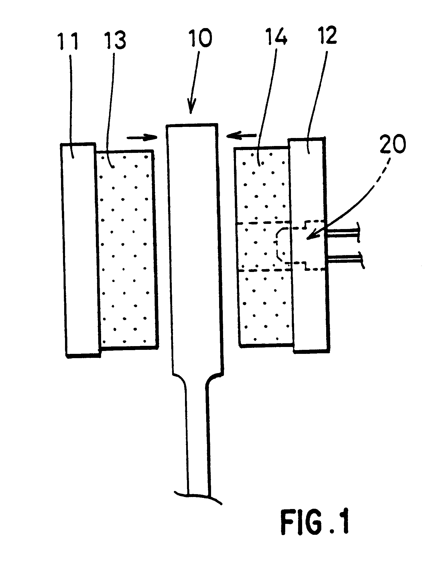
FIG. 1 shows the components of a braking device. The number 10 in FIG. 1 refers to a brake disc, a pair of backplates 11 and 12 being provided on both sides thereof, brake pads 13 and 14 being provided on the backplates 11 and 12 on the sides thereof facing the disc 10. The backplates 11 and 12 are moved towards the disc 10 by a mechanism (not shown), and as a result, the brake pads 13 and 14 press against the disc 10 and frictional force halts the rotation of the disc 10. This is conventional.

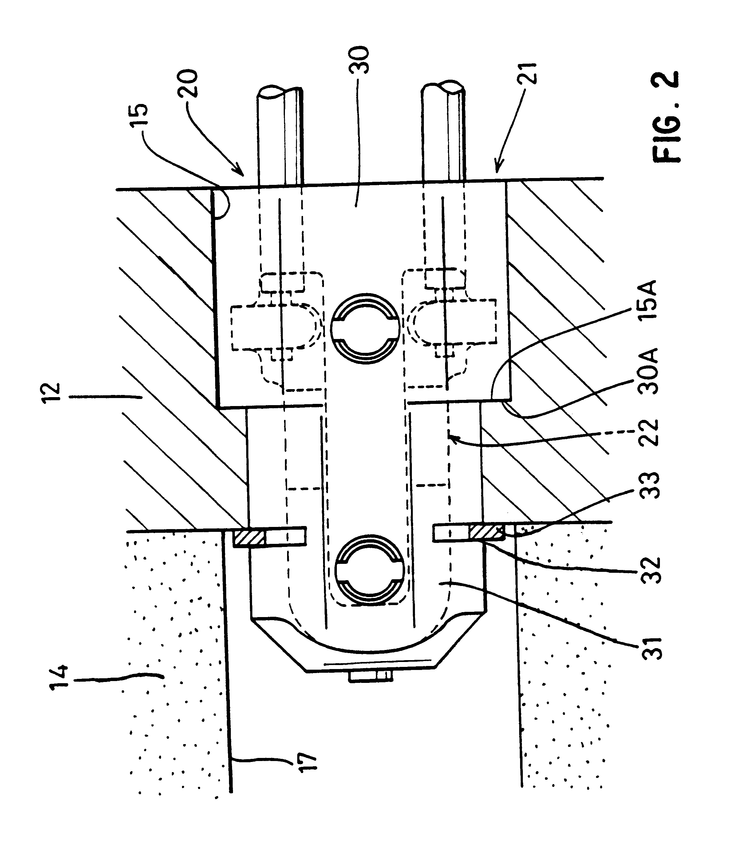
As shown in FIG. 2, an abrasion detecting probe 20 suitable for use in the present invention is attached by being inserted into a through hole 15 formed in a backplate 12, the anterior end of the probe 20 protruding into a through hole 17 formed in the brake pad friction material 14.

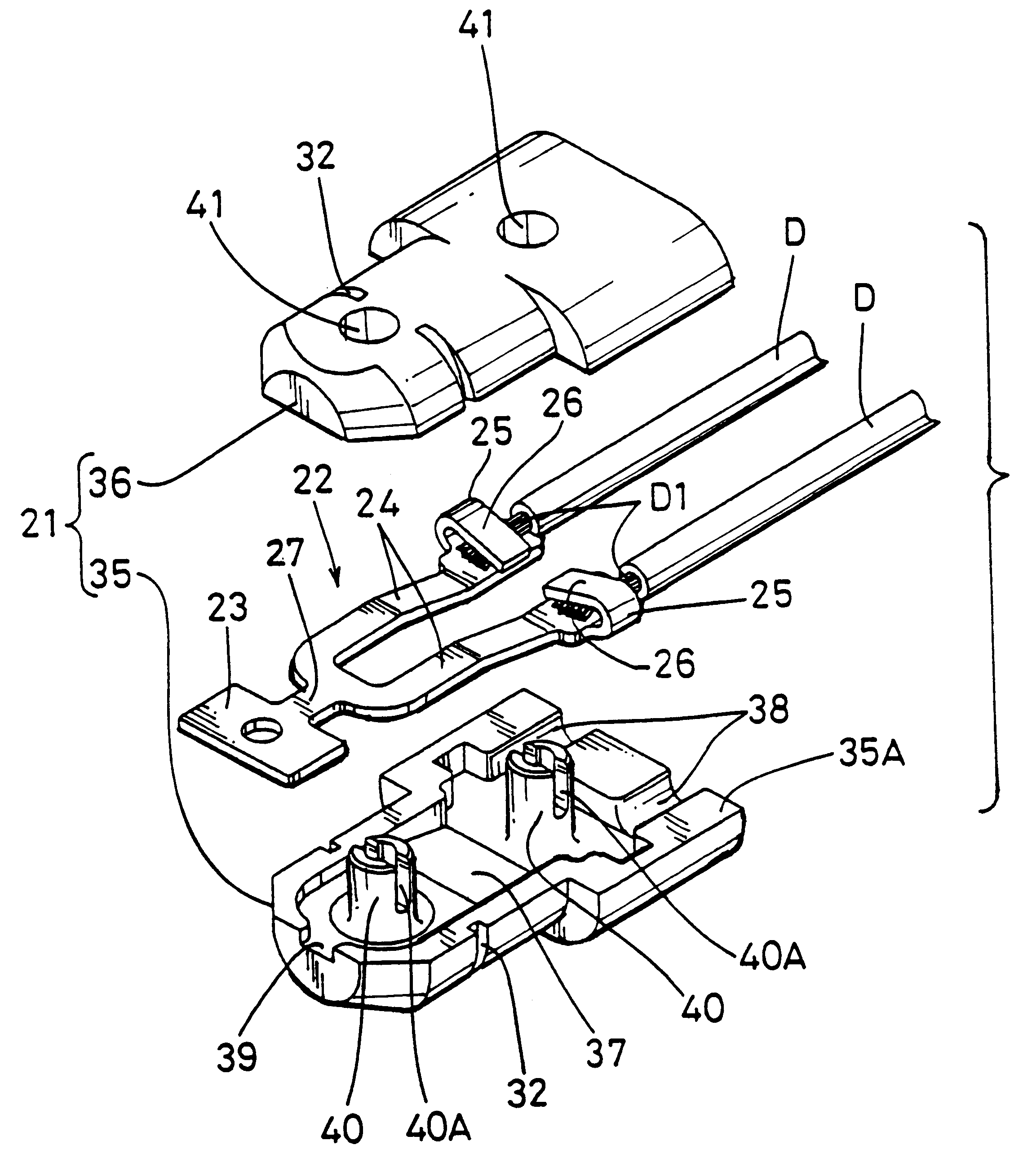
As shown in FIG. 3, the probe 20 is provided with a terminal 22 made of metal and located within a base member 21 of synthetic resin. The terminal 22 is p...

second embodiment

the invention is illustrated in FIGS. 8-10, the same parts having common reference numerals.

As illustrated a sleeve 50 surrounds the base components 35,36, and maintains them in an attached state. The sleeve 50 is a tight push fit over the components 35,36. As illustrated, the sleeve 50 projects slightly beyond the tip 27 of the terminal 22, so that as the pad approaches the abrasion limit, the sleeve 50 rubs against the disc. A bracket 52 holds the probe in the brake pad. The sleeve is made of a material, such as metal, which will make a noise as it is worn away; in this way the driver can hear an audible signal that the abrasion limit is about to be reached.

The sleeve 50 also has the advantage of preventing separation of the components 35,36 during transport from a connector manufacturing location to a brake pad installation location. Furthermore, if the brake pad is replaced when the audible warning is first heard, there is no need to replace the probe itself--the probe can simpl...


PUM


Abstract

The invention provides an abrasion detecting probe for a brake pad which does not require insert-moulding and in which production costs are low.A probe 20 is housed in base components 35 and 36, which are snap-fitted together. In this manner, the terminal 22 can be attached within the base member 21 in a precise predetermined position by the simple operation of joining the base components 35 and 36 together. Therefore, as opposed to a conventional probe, insert-moulding is not required and the probe can be manufactured simply and cheaply. A sleeve 50 may provide an audible brake wear warning.

Description

The present invention relates to an abrasion detecting probe for a brake pad, the probe having a metal terminal inside a synthetic resin base member.BACKGROUND TO THE INVENTIONConventional abrasion detecting probes of this kind include the one described in the JP 6-300064. This type of abrasion detecting probe 1, shown in FIG. 11 hereof, comprises a pair of electric wires D crimped to a metal terminal 2, this terminal 2 being insert-moulded inside a synthetic resin base member 3. The abrasion detecting probe 1 is fixed through a supporting backplate of a brake pad, and when the brake pad attains its abrasion limit as a result of sliding contact with a brake disc, a tip 4 of the probe 1 is worn away together with the brake pad, and the circuit between the two electric wires D is broken.However, because the abrasion detecting probe 1 described above is produced by insert-moulding, position setting of the terminal 2 inside the mould is a troublesome and time-consuming operation which d...

Claims


Application Information

Patent Timeline
Patent Type & Authority Patents(United States)
IPC IPC(8): F16D66/00F16D66/02
CPCF16D66/02F16D66/024
Inventor TAKANASHI, HITOSHIASAO, KAZUHIRO
Owner SUMITOMO WIRING SYST LTD
Why Eureka
Try Eureka