Coating thickness control

Inactive Publication Date: 2001-03-13
HATCH LTD
View PDF17 Cites 84 Cited by
  • Summary
  • Abstract
  • Description
  • Claims
  • Application Information

AI Technical Summary

Problems solved by technology

As such, the over-coating required in order to avoid crossbow induced violations of minimum single spot coating requirements represents a significant cost to continuous galvanising line operators.
All of these prior proposed systems are mechanically relatively complex since they require a multiplicity of controllable operating components provided along the length of the mouth.
This can make t

Method used


Image

  • Coating thickness control
  • Coating thickness control
  • Coating thickness control

Examples


Embodiment Construction

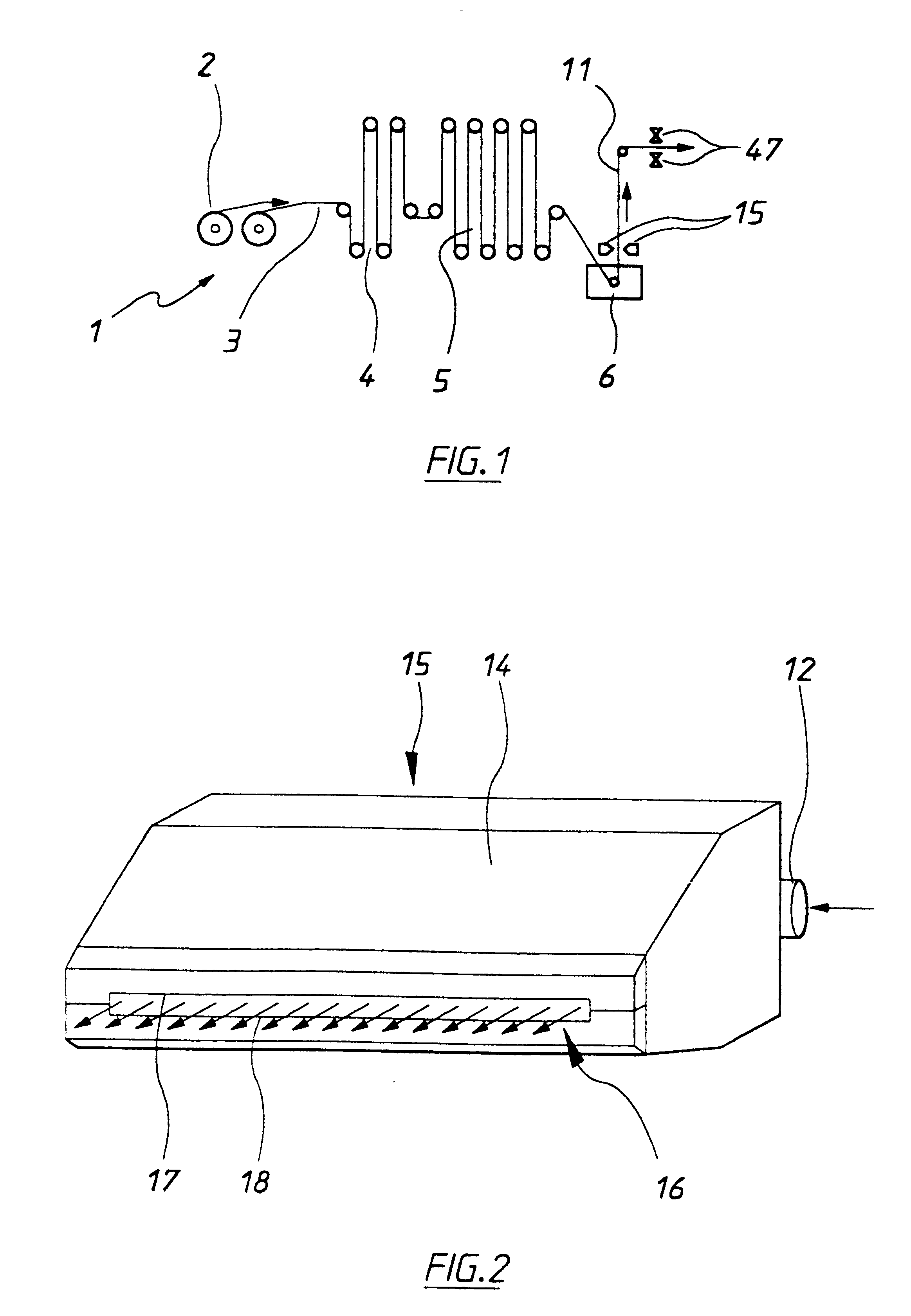
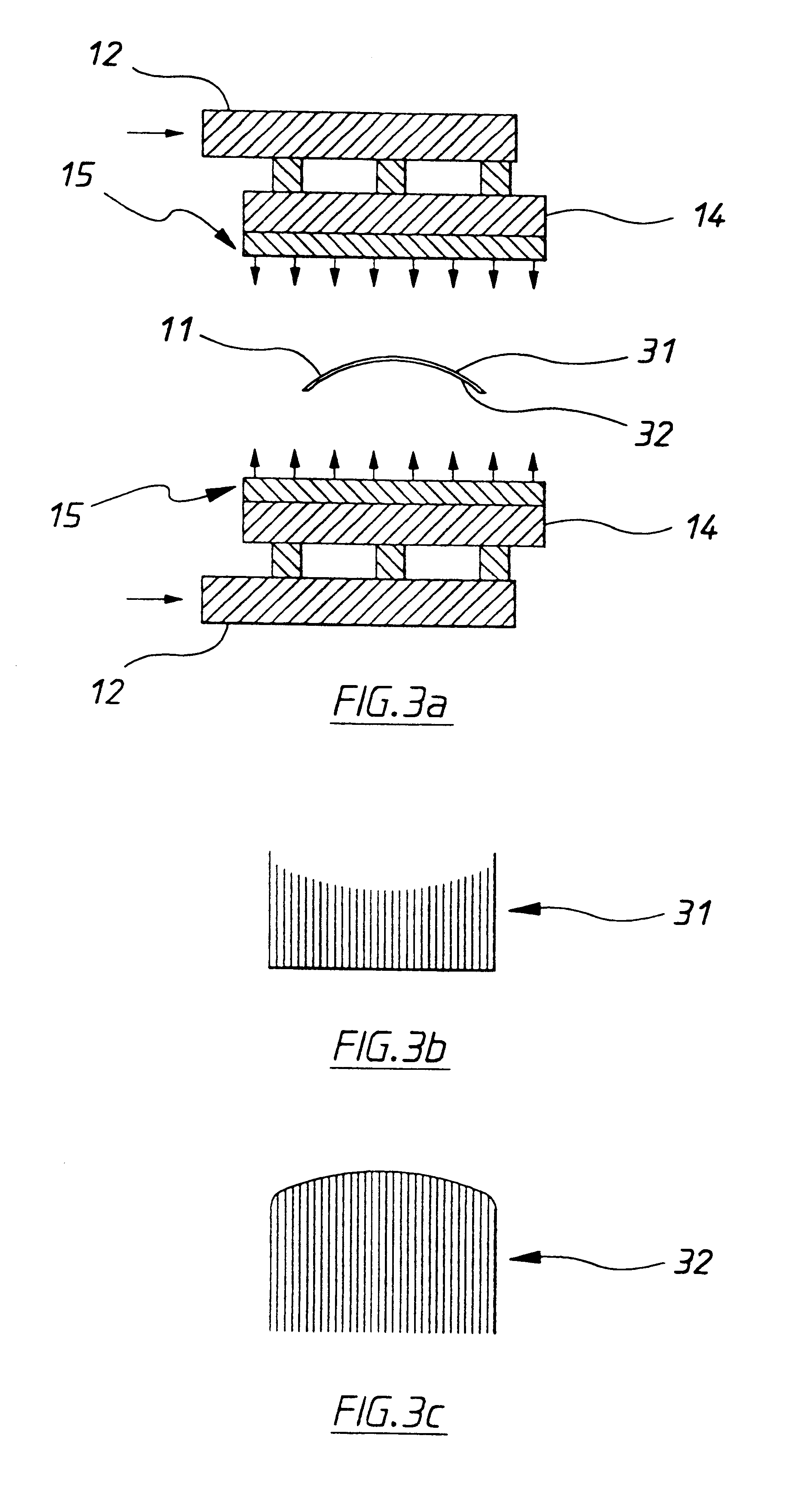
FIGS. 1, 2 and 3 have been referred to in the introductory part of this specification and depict a known hot dip galvanising line, air knife configuration and arrangement, and coating defects caused by bowing of the sheet metal (the crossbow defect).

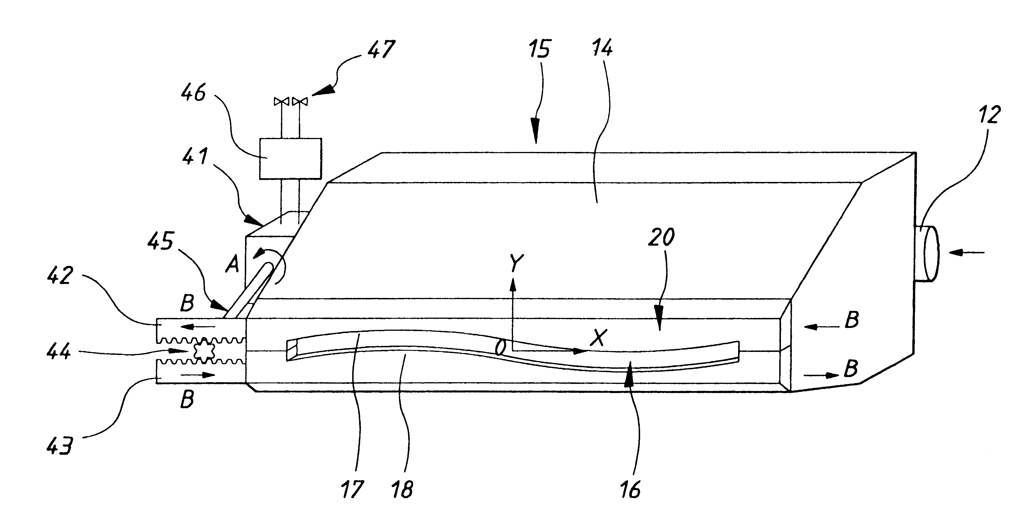
Referring to FIG. 4, the present invention relates to an air knife mouth arrangement 20 for use in an air knife assembly 15 having a laterally extending mouth 16 through which pressurised fluid passes to operate on a coating applied to a surface of a sheet material 11 passing the mouth in a longitudinal direction to control the thickness of the coating. In the preferred form of the invention shown the air knife mouth arrangement 20 comprises a mouth 16 defined by a pair of facing lips 17, 18, each lip having in front elevation a curved shape along its length. The curved shapes of the two lips 17, 18 face each other. The lips 17, 18 of the air knife mouth arrangement are selectively laterally displaceable relative to each other by a movin...


PUM

PropertyMeasurementUnit
Lengthaaaaaaaaaa
Thicknessaaaaaaaaaa
Pressureaaaaaaaaaa

Abstract

An air knife mouth arrangement for use in an air knife assembly having a laterally extending mouth through which pressurized fluid passes to operate on a coating applied to a surface of a sheet material passing the mouth in a longitudinal direction to control the thickness of the coating. In the preferred form of the invention shown the air knife mouth arrangement comprises a mouth defined by a pair of facing lips, each lip having in front elevation a curved shape along its length. The curved shapes of the two lips face each other. The lips of the air knife mouth arrangement are selectively laterally displaceable relative to each other by a moving means so as to thereby vary the separation of the lips and hence the width of the mouth along the length of the mouth. It is to be noted that the term "length" refers to the dimension of the mouth in the lateral direction (indicated by the X axis), while the term "width" refers to the dimension of the mouth in the longitudinal direction (indicated by the Y axis).

Description

This invention relates to the control of thickness of a coating applied to the surface of a sheet material.BACKGROUND TO THE INVENTIONThe accurate and continuous control of the thickness of a coating being applied to the surface of a sheet material is required in a number of industries. For example, it is often necessary to control the thickness of coatings applied to paper or other similar materials in the form of a continuous travelling web. Another field in which the control of thickness of a continuously applied coating is required is in hot dip galvanising of metal sheet. The present invention has been particularly developed for controlling the coating thickness in a hot dip galvanising operation and it will be convenient to particularly describe the invention in relation to this field of application. However it should be appreciated that the apparatus and process of the present invention is applicable to other coatings and to other sheet materials being coated.The hot dip galv...

Claims


Application Information

Patent Timeline
IPC IPC(8): B05C11/06B05C11/02C23C2/14C23C2/20D21H25/16D21H25/00B05C11/04B05B15/00
CPCB05C11/06C23C2/20D21H25/16
Inventor WALLACE, GLEN
Owner HATCH LTD
Why Eureka
Try Eureka