
Integrated gaze/manual cursor positioning system

Inactive Publication Date: 2001-03-20
TOBII TECH AB
View PDF18 Cites 303 Cited by
  • Summary
  • Abstract
  • Description
  • Claims
  • Application Information

AI Technical Summary

Problems solved by technology

Although computer mouses are practically essential with today's computers, intense use can cause fatigue and repetitive motion injury.
Despite these limitations, further improvement of mouse-activated target selection systems has been difficult.
One problem with these systems is that humans use their the eyes naturally as perceptive, not manipulative, body parts.
Eye movement is often outside conscious thought, and it can be stressful to carefully guide eye movement as required to accurately use these target selection systems.
For many operators, controlling blinking or staring can be difficult, and may lead to inadvertent and erroneous target selection.
Thus, although eye gaze is theoretically faster than any other body part, the need to use unnatural selection (e.g., by blinking or staring) limits the speed advantage of gaze controlled pointing over manual pointing.
Another limitation of the foregoing systems is the difficulty in making accurate and reliable eye tracking systems.
Only relatively large targets can be selected by gaze controlling pointing techniques, because of eye jitter and other inherent difficulties in precisely monitoring eye gaze.
Consequently, known gaze-based target selection systems are not adequate for some applications due to certain unsolved problems.
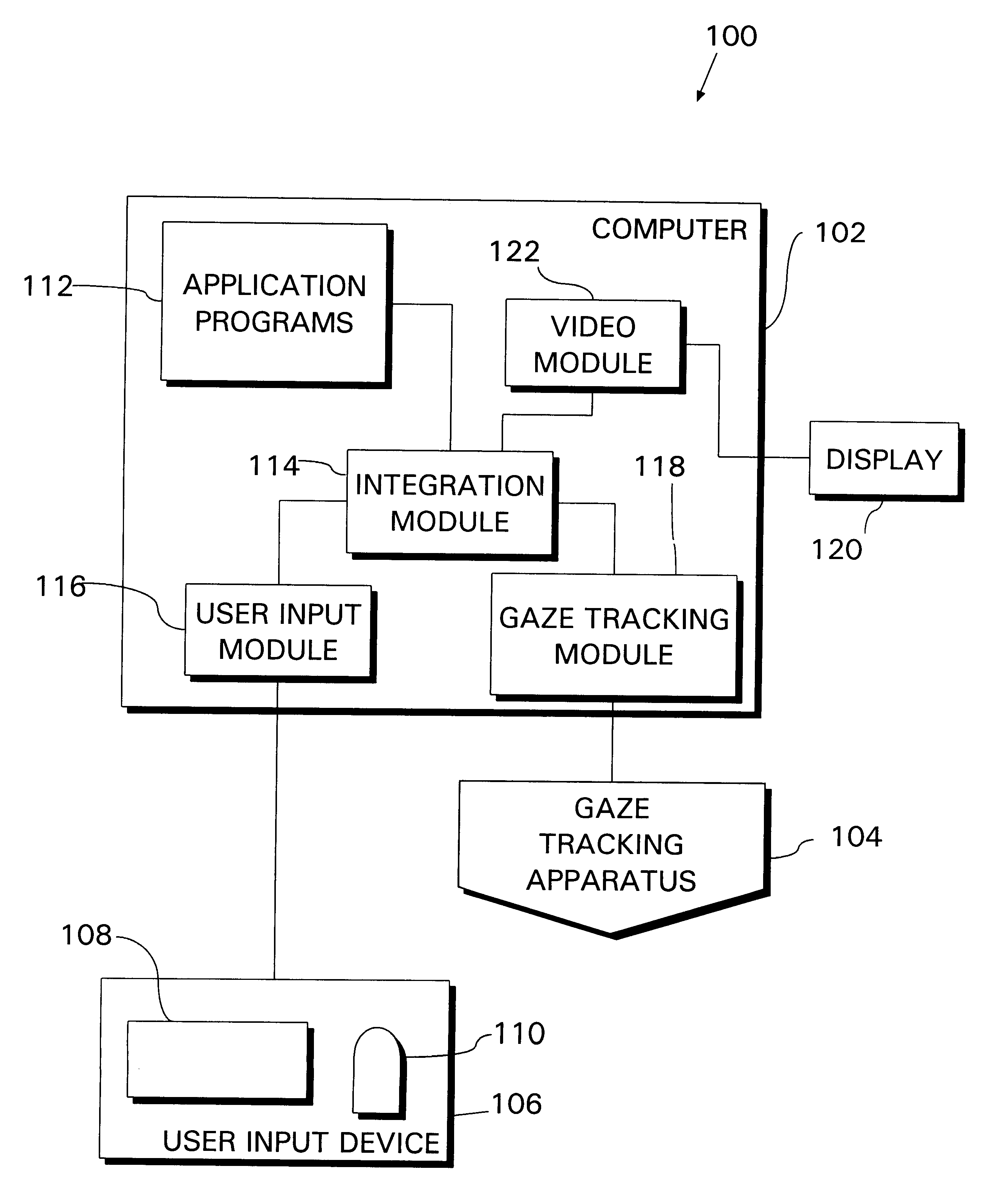
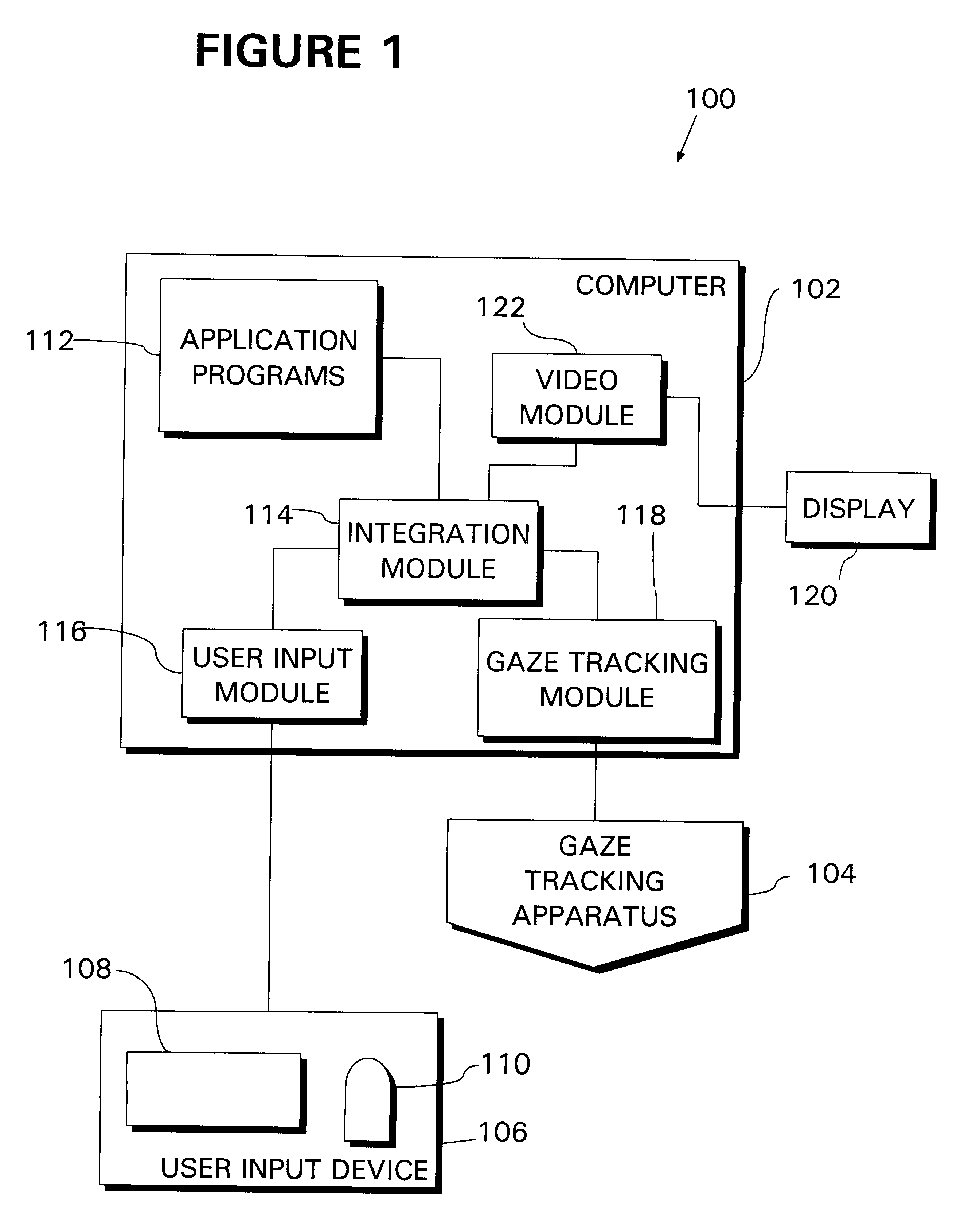
This calculated point may include some error due to the limits of resolution of the gaze tracking apparatus 104, intrinsic difficulties in calculating gaze (e.g., accounting for head movement in corneal reflection systems, etc.), and other sources of error.

Method used


Image

  • Integrated gaze/manual cursor positioning system
  • Integrated gaze/manual cursor positioning system
  • Integrated gaze/manual cursor positioning system

Examples


Embodiment Construction

While the foregoing disclosure shows a number of illustrative embodiments of the invention, it will be apparent to those skilled in the art that various changes and modifications can be made herein without departing from the scope of the invention as defined by the appended claims. Furthermore, although elements of the invention may be described or claimed in the singular, the plural is contemplated unless limitation to the singular is explicitly stated.


PUM


Abstract

A computer-driven system aids operator positioning of a cursor by integrating eye gaze and manual operator input, thus reducing pointing time and operator fatigue. A gaze tracking apparatus monitors operator eye orientation while the operator views a video screen. Concurrently, the computer monitors an input device, such as a mouse, for mechanical activation by the operator. According to the operator's eye orientation, the computer calculates the operator's gaze position. Also computed is a gaze area, comprising a sub-region of the video screen that includes the gaze position. This region, for example, may be a circle of sufficient radius to include the point of actual gaze with a certain likelihood. When the computer detects mechanical activation of the operator input device, it determines an initial cursor display position within the current gaze area. This position may be a predetermined location with respect to the gaze area, such as a point on the bottom of the gaze area periphery. A different approach uses the initial mechanical activation of the input device to determine the direction of motion, and sets the initial display position on the opposite side of the gaze area from this motion so that continued movement of the input device brings the cursor to the gaze position in a seamless transition between gaze and manual input. After displaying the cursor on the video screen at the initial display position, the cursor is thereafter positioned manually according to the operator's use of the input device, without regard to gaze.

Description

1. Field of the InventionThe present invention relates to video cursor positioning systems. More particularly, the invention concerns a system for positioning a cursor on a video screen, in which pointing time and operator fatigue are reduced by integrating eye gaze tracking and manual operator input.2. Description of the Related ArtIn human-computer interaction, one of the most basic elements involves selecting a target using a pointing device. Target selection is involved in opening a file with a mouse "click", activating a world wide web link, selecting a menu item, redefining a typing or drawing insertion position, and other such operations. Engineers and scientists have developed many different approaches to target selection. One of the most popular target selection devices is the computer mouse. Although computer mouses are practically essential with today's computers, intense use can cause fatigue and repetitive motion injury.Despite these limitations, further improvement of ...

Claims


Application Information

Patent Timeline
IPC IPC(8): G06F3/00G06F3/033G06F3/01G06F3/038
CPCG06F3/013G06F3/038G06F2203/0381
Inventor AMIR, ARNONFLICKNER, MYRON DALEIHDE, STEVEN CARLYLEZHAI, SHUMIN
Owner TOBII TECH AB
Learn More