Quick change blade assembly for a rotary mower

Inactive Publication Date: 2001-03-27
BRIGGS & STRATTON POWER PRODS GROUP
View PDF23 Cites 43 Cited by
  • Summary
  • Abstract
  • Description
  • Claims
  • Application Information

AI Technical Summary

Problems solved by technology

This can be difficult when there has been a build-up of debris around the blade bolt or when moisture has caused rust which locks the bolt in place.
Also, it can be hazardous if

Method used


Image

  • Quick change blade assembly for a rotary mower
  • Quick change blade assembly for a rotary mower
  • Quick change blade assembly for a rotary mower

Examples


Embodiment Construction

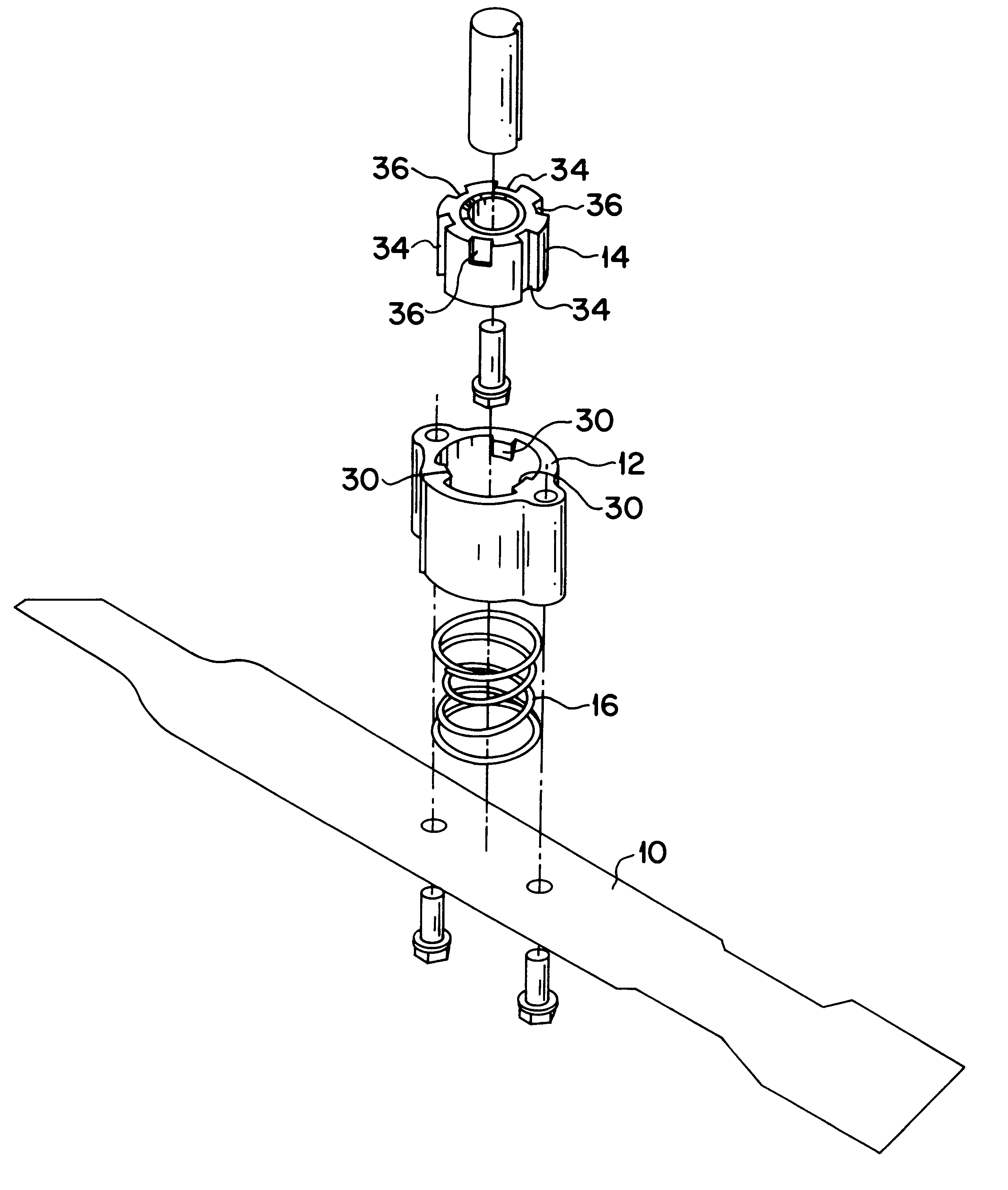
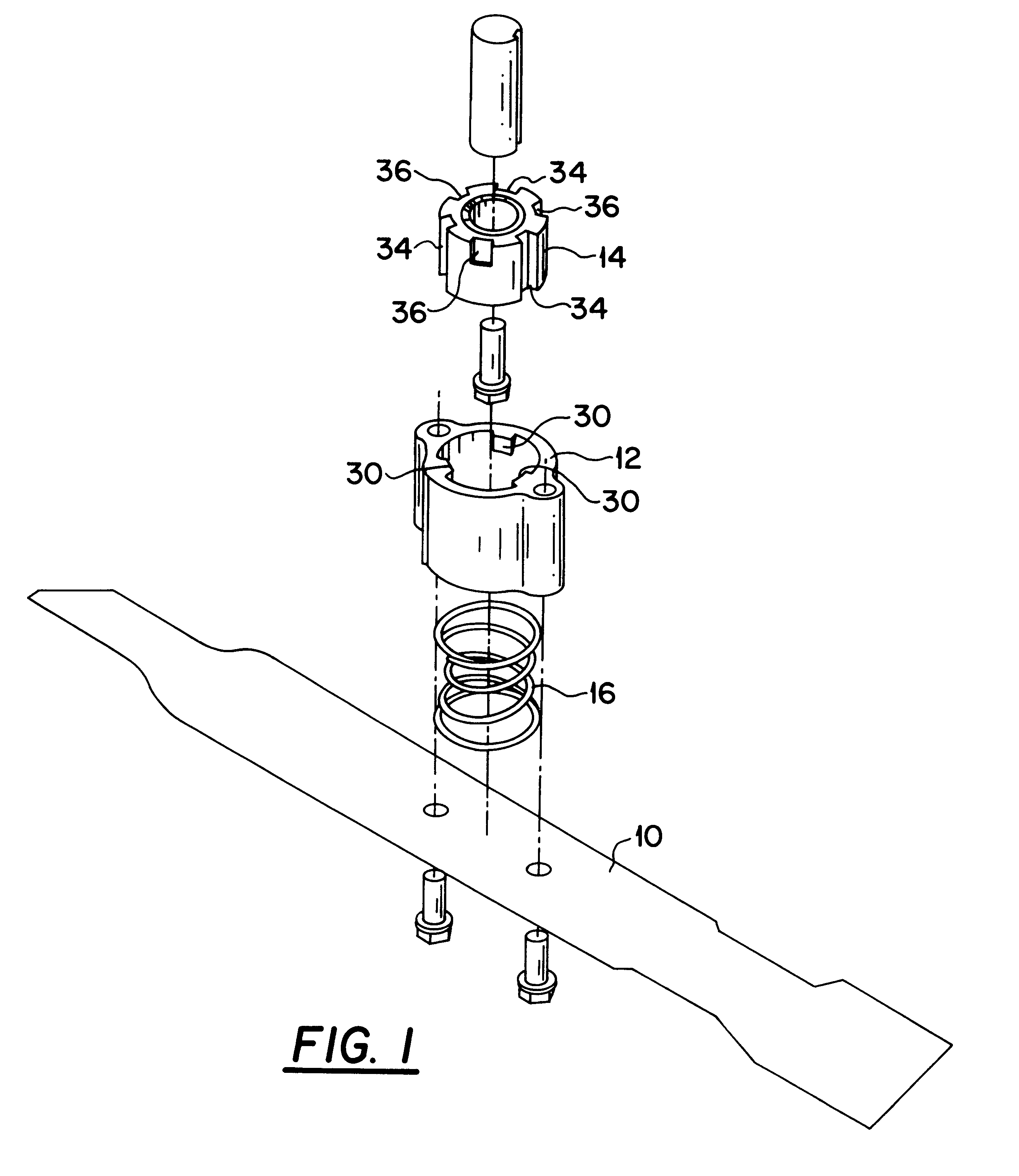
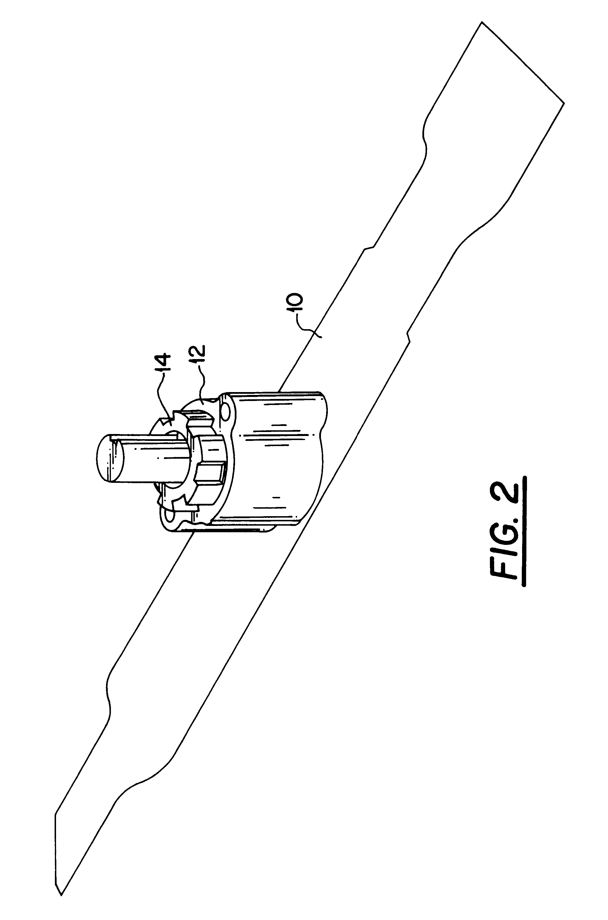
Referring to FIG. 1, the invention consists of four basic components: a blade 10, a blade adapter 12, a fixed adapter 14 and a compression spring 16.

The blade adapter 12 (shown in greater detail in FIG. 4) comprises a substantially cylindrical element 18 having diametrically opposed outer ears 20 and 22 which are provided with internally threaded bores 24 and 26, respectively. These bores permit blade 10 to be secured to the blade adapter 12 by bolts, as can be appreciated from FIG. 1. A substantially cylindrical inner wall 28 of element 18 is provided with a plurality of inwardly projecting, and equally spaced, ears 30 which have lengths corresponding to a portion of the length of element 18.

The fixed adapter 14 (shown in greater detail in FIG. 5) comprises a generally cylindrical body 32 having an outer diameter which is slightly less than the inner diameter of the blade adapter 12 defined by the inner wall 28 of element 18 (FIG. 4). The outer wall of body 32 is provided with groo...


PUM


Abstract

A blade is secured to a blade adapter which is dimensioned to receive a fixed adapter. The fixed adapter is connected to the engine drive shaft of a rotary mower. The blade and fixed adapter are provided with cooperating surfaces which permit the adapters to be selectively locked together and separated from each other without requiring tools.

Description

1. Field of the InventionThe present invention relates to an assembly which permits a blade to be attached to and removed from a rotary mower without the use of tools.2. Prior ArtCurrently, to sharpen or replace a mower blade for a rotary mower requires that the blade be removed from the mower using a wrench or socket to loosen a bolt which secures the blade to the mower. This can be difficult when there has been a build-up of debris around the blade bolt or when moisture has caused rust which locks the bolt in place. Also, it can be hazardous if the wrench or socket slips off the bolt's head during blade attachment or removal thereby causing one's hand to strike the mower blade housing or the sharpened edge of the blade.The present invention provides a mower blade assembly which permits the blade of a rotary mower to be attached to and removed from the mower without the use of tools. This is accomplished by securing the blade to a blade adapter and securing a fixed adapter to the m...

Claims


Application Information

Patent Timeline
IPC IPC(8): A01D34/73
CPCA01D34/733
Inventor BONTRAGER, ROBERT C.PITMAN, RICHARD J.SCOTT, PAUL L.
Owner BRIGGS & STRATTON POWER PRODS GROUP
Why Eureka
Try Eureka