Paper-feeding apparatus and method of feeding paper

a paper feeding and paper feeding technology, applied in the field of paper feeding apparatus and paper feeding method, can solve the problems of paper feeding often failing, apparatuses cannot ensure, and create a gap between the flat surface and the brake sho

Inactive Publication Date:
View PDF7 Cites 83 Cited by
  • Summary
  • Abstract
  • Description
  • Claims
  • Application Information

AI Technical Summary

Problems solved by technology

When not feeding the print medium, the flat surface of the feeding roller opposes the brake shoe, creating a gap between the flat surface and the brake shoe.
However, the aforementioned conventional paper-feeding apparatuses cannot ensure that print medium of various kinds such as thin paper, thick paper, envelopes and so on is advanced one page at a time.
In general, a plurality of pages tend to be advanced simultaneously when thin print medium is fed while paper feeding often fails when thick print medium is fed.
Pressing the brake shoe against the feeding roller with a larger force in an attempt to prevent multi-page feeding will cause failure of a paper feeding operation if the print medium is thick.

Method used


Image

  • Paper-feeding apparatus and method of feeding paper
  • Paper-feeding apparatus and method of feeding paper
  • Paper-feeding apparatus and method of feeding paper

Examples


first embodiment

Construction

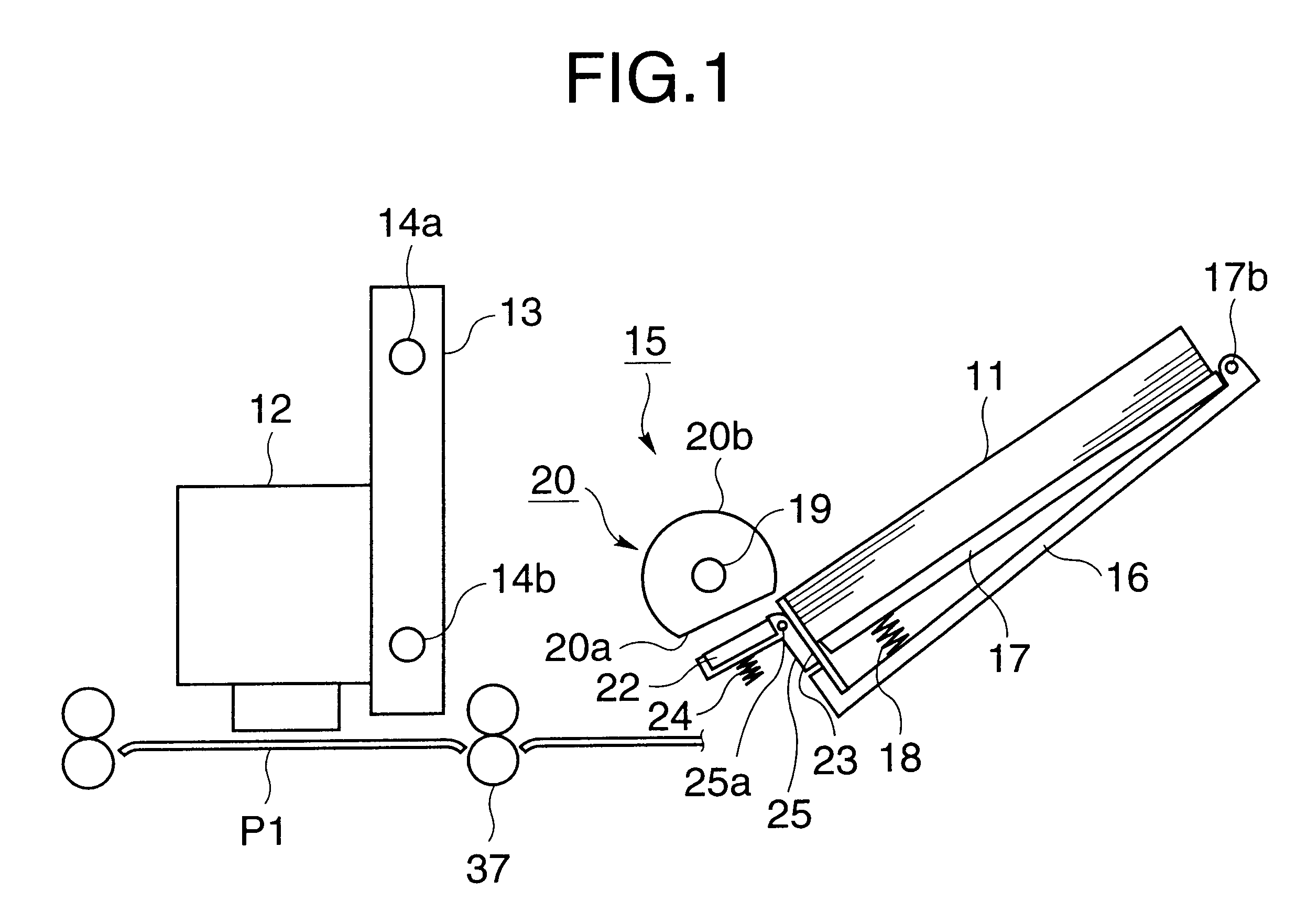
FIG. 1 illustrates a general construction of a paper-feeding apparatus according to a first embodiment.

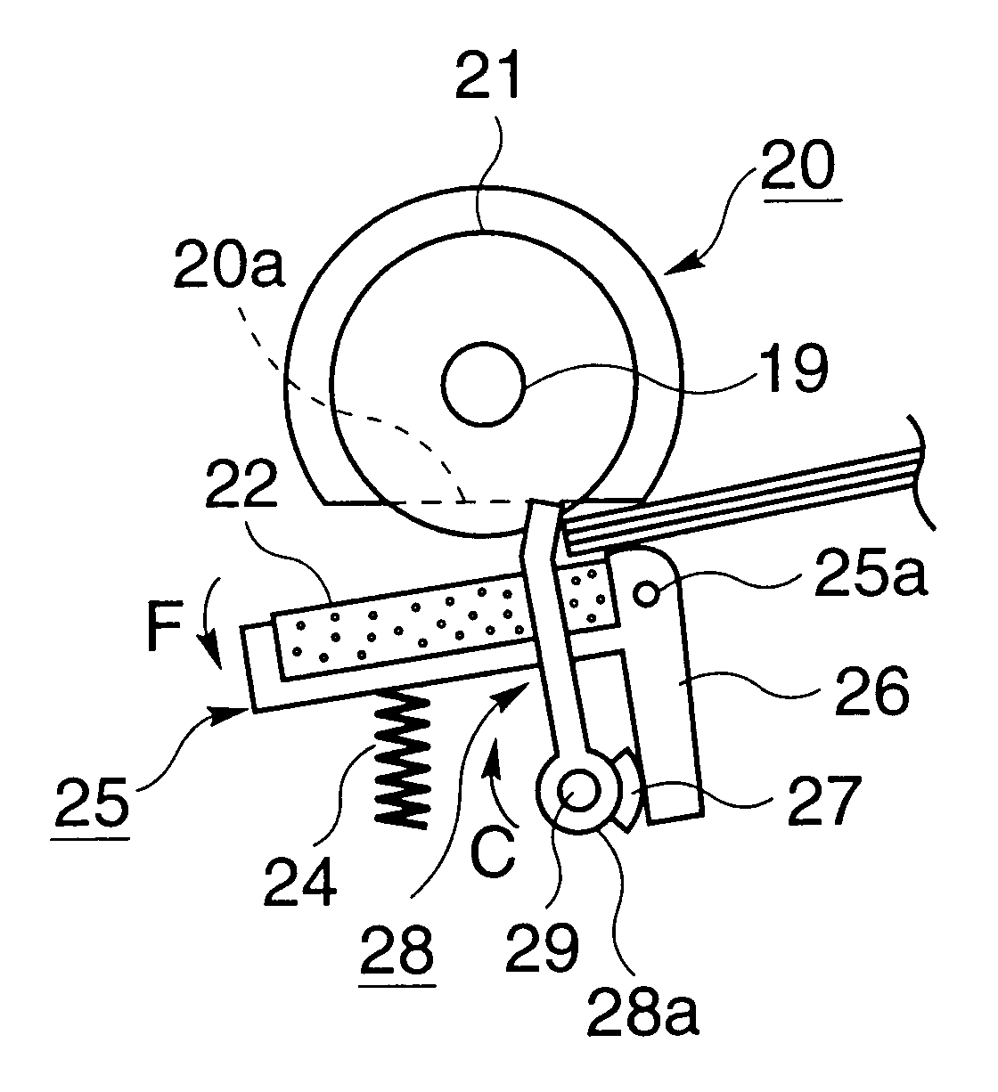
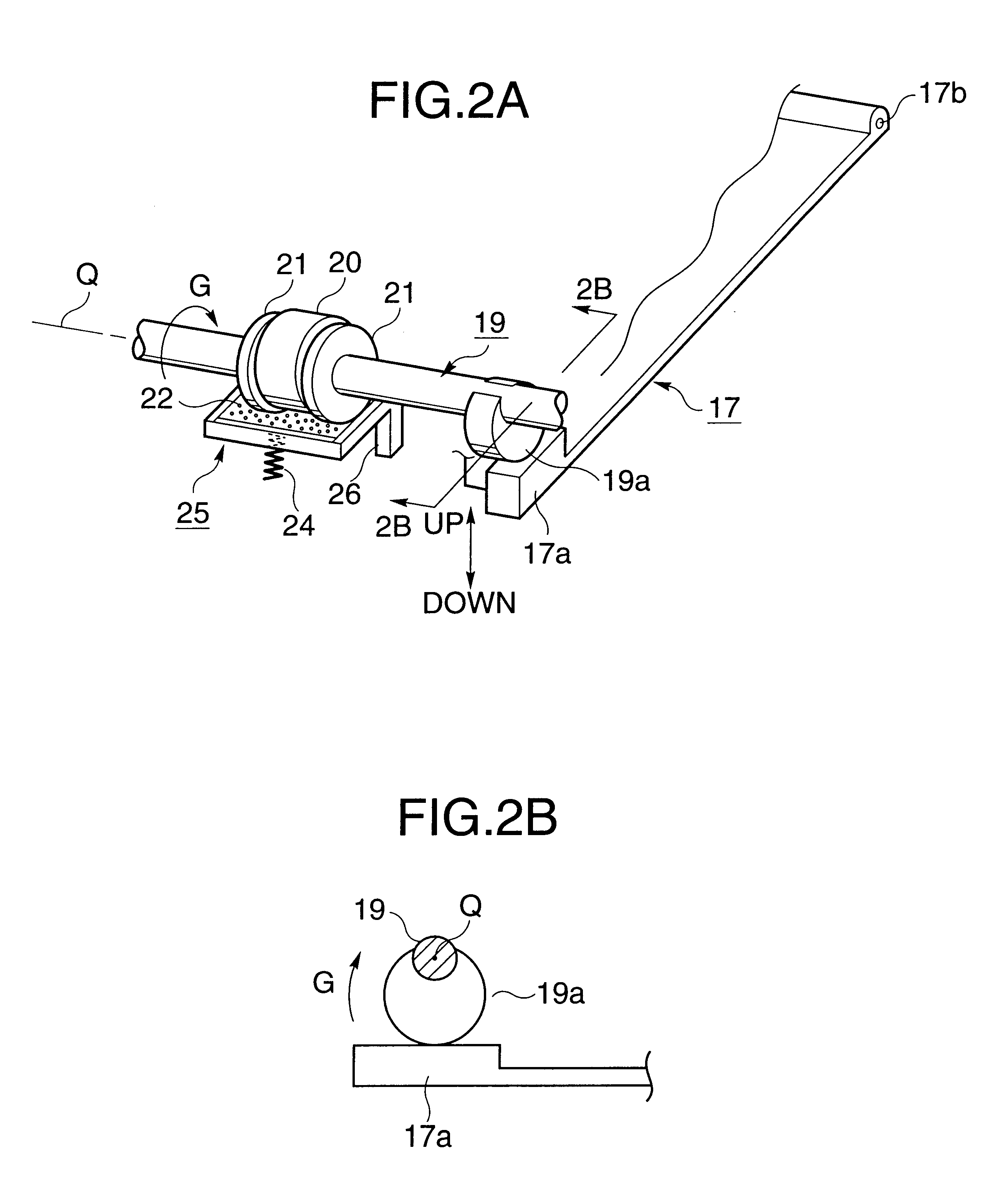
Referring to FIG. 1, a carriage 13 runs on two parallel guide shafts 14a and 14b. The carriage 13 supports a print head 12 thereon. A paper feeding apparatus 15 includes a base frame 16, platform 17, pressure spring 18, feeding roller 20, and brake shoe 22. A stack of print medium 11 such as thin paper, thick paper, and envelopes is accommodated in the base frame 16 inclined at an angle with the horizontal. The base frame 16 supports the platform 17 thereon. The platform 17 supports the stack of print medium 11 thereon and is pivotal about a pin 17b relative to the base frame 16. The platform 17 is urged upward by the pressure spring 18 disposed on the bottom of the base frame 16, so that the top page of the print medium 11 is pressed against the feeding roller 20.

The feeding roller 20 rotates on a shaft 19 disposed near the forward end of the base frame 16. The feeding...

second embodiment

Construction

Elements of the same construction as those of the first embodiment have been given the same reference numerals and description thereof is omitted.

FIG. 12 is a side view of the paper feeding apparatus when it is at a "low pressure position."

FIG. 13 is a side view of the paper feeding apparatus when it is at a "high pressure position."

Referring to FIGS. 12 and 13, the compression 24 urges the brake shoe 22 against the feeding roller 20. The spring 24 is substantially vertically mounted between the holders 40 and 42. The holder 40 is pivotally mounted to the base frame 16 by means of a pin 40a in the similar manner that the holder 25 is mounted to the base frame 16 as shown in FIG. 1. The holder 42 is also pivotally mounted to the base frame 16 by means of a pin 42a.

A cam shaft 43 is rotatably supported by the base frame 16 and has a cam 43a fixedly mounted to the cam shaft 43. The cam 43a is located under the holder 42. When the cam shaft 43 is rotated in a direction shown...


PUM

PropertyMeasurementUnit
pressureaaaaaaaaaa
frictional forceaaaaaaaaaa
diameteraaaaaaaaaa

Abstract

A paper-feeding apparatus is used for feeding print medium from a paper cassette. The paper cassette holds a stack of print paper therein. The feeding roller is disposed close to a forward end of the paper cassette. The feeding roller engages a top page of the stack of print paper to feed the top page from the paper cassette to a printing area. The paper separator engages the feeding roller to cooperate with the feeding roller to separate the top page from the stack of print paper. The paper-positioning member is, for example, an arm. When the feeding roller is not feeding the print medium, the arm pushes back the forward ends of pages of print medium toward the rear end of the paper cassette, thereby aligning the forward ends of the pages of the stack of print paper. The paper feeding apparatus may further have an urging member, e.g., a spring, which urges the paper separator against the feeding roller, and an urging-force-changing member, e.g., a cam that changes an urging force of the urging member. When the cam rotates to a high-pressure position, the cam pushes the spring to cause the spring to urge the medium separator against the feeding roller with a larger force. When the cam rotates to a low-pressure position, the cam pushes the spring to cause the spring to urge the medium separator against the feeding roller with a smaller force.

Description

1. Field of the InventionThe present invention relates to a paper-feeding apparatus and a method of feeding paper.2. Description of the Related ArtConventional paper-feeding apparatuses are of a construction where a platform or sheet guide frame is pushed upward by the urging force of a pressure spring so that the print medium placed on the platform is pressed against a feeding roller. A controller provides an instruction to a paper-feeding motor and the paper-feeding motor drives the feeding roller into rotation to advance the print medium from the platform.When feeding the print medium from the platform, a plurality of pages of print medium may be advanced simultaneously by chance from the platform. In order to prevent such a simultaneous advancement of pages, a separator wall is provided which is formed of a film and located at the forward end of the platform. The separator wall obstructs the plurality of pages and allows only the top page to be fed. There is also provided a brak...

Claims


Application Information

Patent Timeline
Patent Type & Authority Patents(United States)
IPC IPC(8): B65H3/52B65H9/10B65H3/46B41J13/00
CPCB65H3/5223B65H3/565B65H9/101B65H2301/42324B65H2301/42344B65H2404/1112B65H2405/1117B65H2405/113
Inventor YAMAZAKI, KEIICHIRO
Why Eureka
Try Eureka