
Plantar fascitis support apparatus

a support device and plantar fascitis technology, applied in the field of plantar fascitis support devices, can solve the problems of inadequate adjustment, debilitating plantar fascitis, and very painful everyday activities such as walking and standing

Inactive Publication Date: 2001-05-08
MEDICAL SPECIALTIES
View PDF14 Cites 19 Cited by
  • Summary
  • Abstract
  • Description
  • Claims
  • Application Information

AI Technical Summary

Benefits of technology

to provide a plantar fascitis support apparatus which is lightweight and comfortable within conventional footwear.
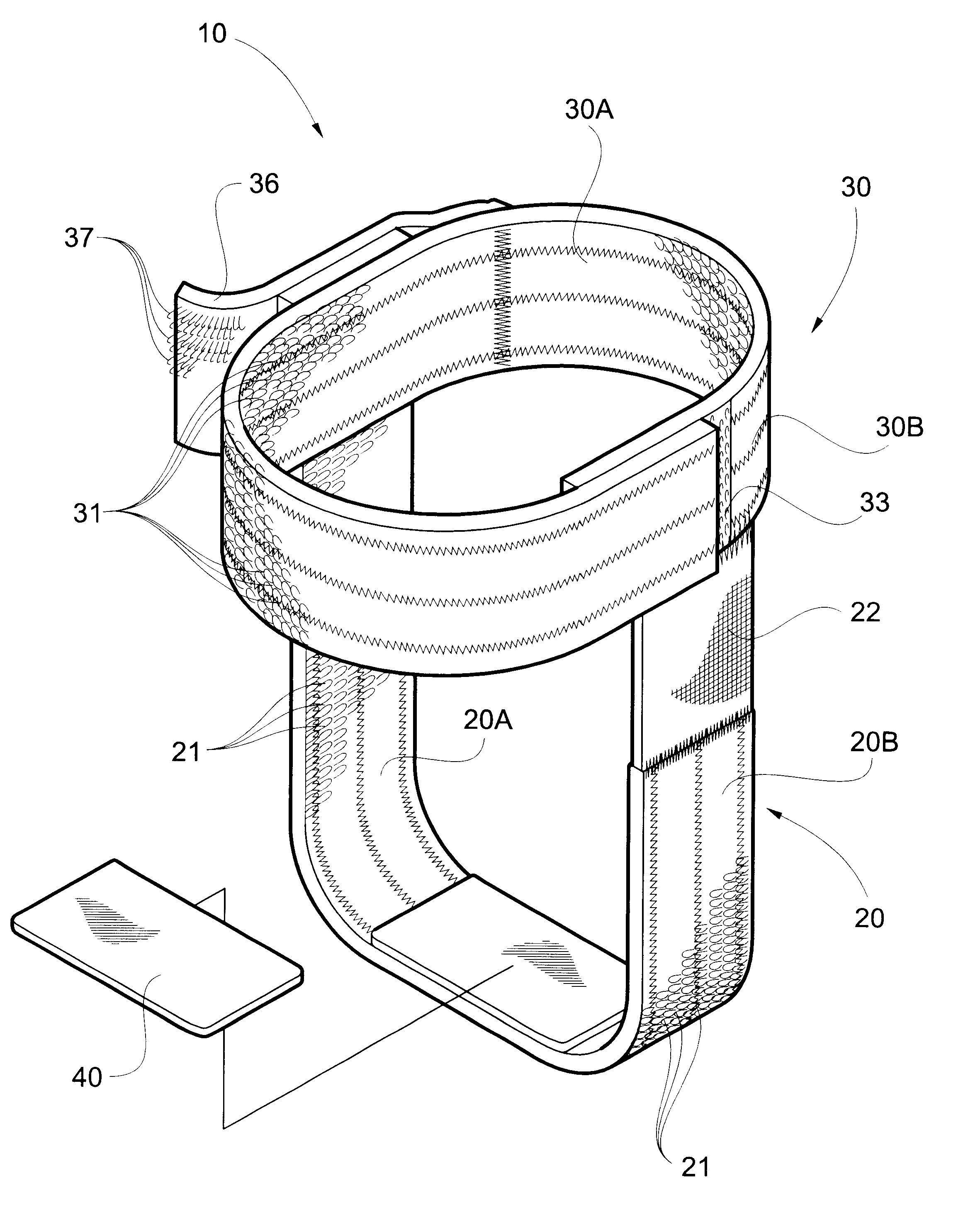
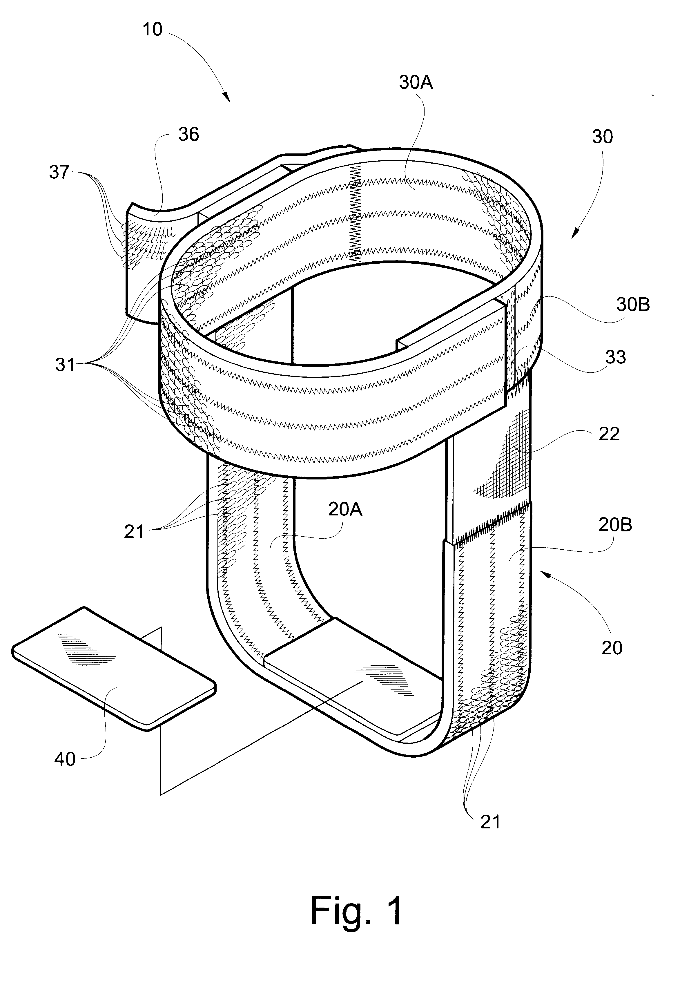
The pad 40 is preferably adjustable and removable. For this purpose, a patch 42 of hooks is attached by adhesive or other means to one surface of the pad 40, as shown in FIG. 6. The patch 42 cooperates with the loops 21 on the inner surface 20A at the bottom of the "U" to secure the pad 40 is the desired position. The pad 40 is fabricated of a suitable weight and density of a foam material. The pad 40 can be easily repositioned when desired or removed altogether for replacement or when laundering the plantar fascitis support apparatus.

Problems solved by technology

Plantar fascitis can be quite debilitating in that everyday activities such as walking and standing are very painful.
Some conventional supports are either too bulky to be easily worn with footwear, or so flimsy that too little support is provided, inadequate adjustment is provided, or the support loses proper adjustment during wear.

Method used


Image

  • Plantar fascitis support apparatus
  • Plantar fascitis support apparatus
  • Plantar fascitis support apparatus

Examples


Embodiment Construction

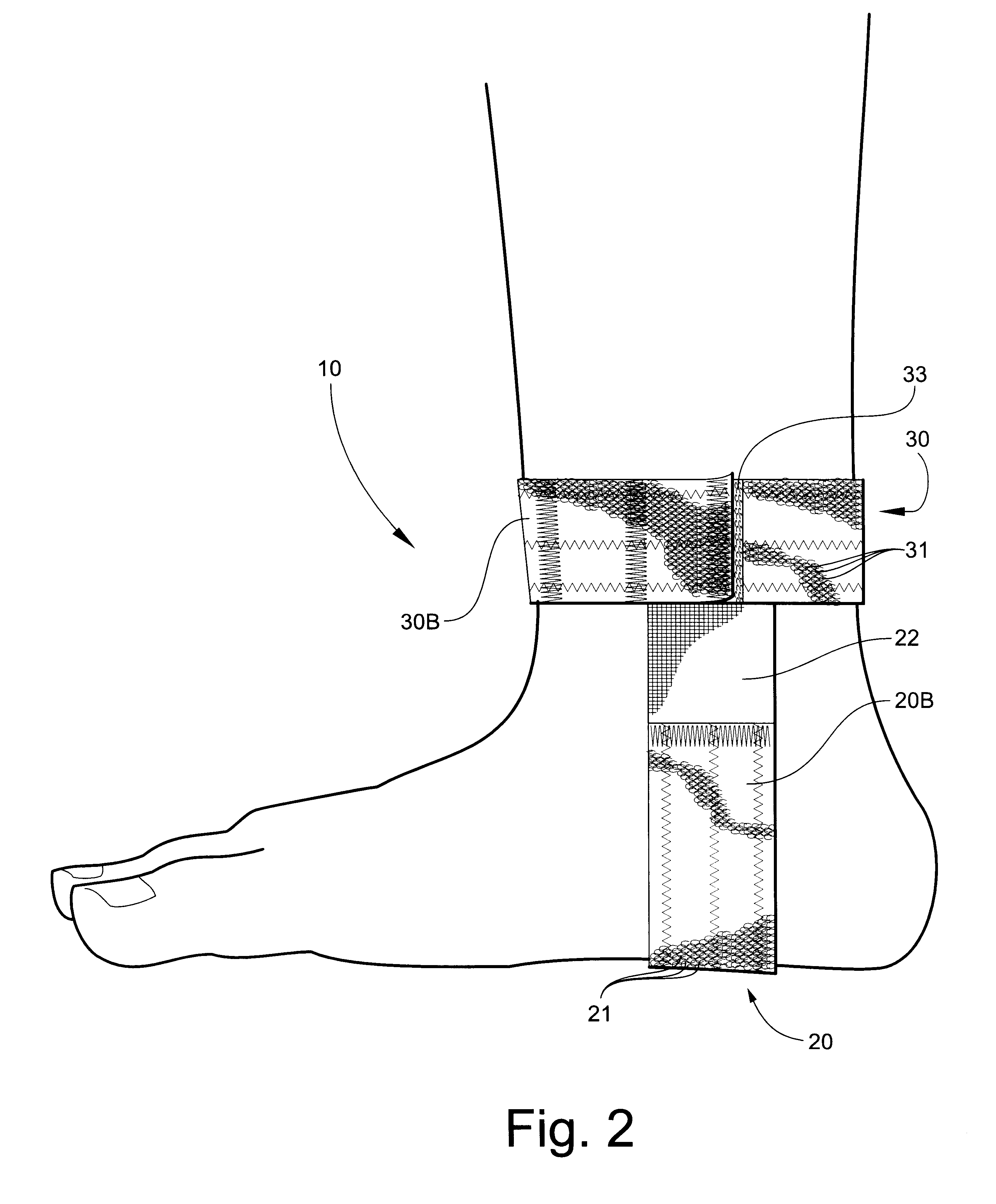
Referring now specifically to the drawings, a plantar fascitis support apparatus according to the present invention is illustrated in FIG. 1 and shown generally at reference numeral 10. The plantar fascitis support apparatus 10 is constructed of two principal elements, a support strap 20 and a retention strap 30 which intersect and connect with each other at a substantially right angle to each other. As is shown in FIGS. 2-5, the support strap 20 extends in a generally "U" shaped configuration under the bottom of the foot and extends upwardly along the medial and lateral aspects of the foot. Optionally, a pad 40 is positioned in the bottom of the "U" and directly engages the plantar fascia in the arch of the foot anterior of the heel. The support strap 20 is maintained in its proper support position by the retention strap 30, which encircles the ankle. Proper adjustment is essential if the plantar fascitis support apparatus 10 is to perform its intended therapeutic functions.

Both th...


PUM


Abstract

A plantar fascitis foot support apparatus, including a support strap for being positioned in a generally U-shaped configuration along the medial and lateral aspects of the ankle and extending under and supporting the plantar fascia region of the foot. An ankle-encircling retention strap is attached by its opposite ends to the support strap at a substantially right angle thereto for retaining the support strap in a supporting position against the plantar fascia region. The support strap includes an inelastic segment and at least one attached elastic segment for providing controlled stretch of the support strap during placement on the foot and during subsequent movement of the foot while the support is in place. Complementary and releasably-adjustable fastener elements are carried by the retention strap and the support strap for permitting lengthwise adjustment of the support strap relative to the plantar fascia region of the foot. The fastener elements include a first fastener element carried by an outer surface of the retention strap, a second fastener element carried by an inner surface of the support strap for being adjustably-mated with the first fastener element for retaining the support strap and the retention strap in a desired position relative to each other, and a third fastener element carried on an outer surface of the support strap. A fastener cover is carried by the retention strap and has a fourth fastener element carried on an inner surface thereof for mating with the third fastener element of the support strap.

Description

TECHNICAL FIELD AND BACKGROUND OF THE INVENTIONThis invention relates to a plantar fascitis support apparatus with support and adjustment features which enhance the comfort, adjustability and support provided by the apparatus. Plantar fascitis is a medical condition characterized by a tear in the arch ligament, or plantar fascia, on the bottom of the human foot. The plantar fascia extends from the base of the heel bone to each of the toes of the foot. Plantar fascitis results when, either suddenly or gradually, motion and / or lack of arch support causes the flattening of the arch or the spreading of the toes such that sufficient pressure is exerted on the bottom of the foot to tear the plantar fascia. Injury often occurs as the result of hyperextension of the toes in the upward direction during exercise.Plantar fascitis can be quite debilitating in that everyday activities such as walking and standing are very painful. Typically, most pain is experienced in the heel area, where the p...

Claims


Application Information

Patent Timeline
Patent Type & Authority Patents(United States)
IPC IPC(8): A61F5/01
CPCA61F5/0113
Inventor GAYLORD, ROBERT SCOTTGRIFFIN, DONALD EARL
Owner MEDICAL SPECIALTIES
Learn More