Multi-purpose traveling luggage

Inactive Publication Date: 2001-05-29
ISABELITA HILARIO CHEN
View PDF11 Cites 70 Cited by
  • Summary
  • Abstract
  • Description
  • Claims
  • Application Information

AI Technical Summary

Benefits of technology

Further, it is another objective of the present invention to provide a multi-purpose traveling luggage which can instantly be converted from a normal luggage into a pulling luggage or a luggage that carries other luggage(s). This multi-purpose traveling luggage is fast and convenient for a traveler.
Additionally, there is a pair of drive rod members. The lower portions of the drive rod members are fixedly connected to the lower portions of the backboard at the outer edges. The upper portions of the drive rod members are connected to each other by a connecting rod member, which slidably engages in the leg supports to form a scissor-like support frame. The drive rod members telescopically receive a pair of extension rods, which are united by a handle bar to facilitate the pushing or pulling of the scissor-like support frame.
In addition, there is a hook lock located in the middle of the upper portion of the back side of the backboard which can lock the drive rod members in a closed position or release the drive rod members from such a position. There are also two L-shaped hooks located at the two shoulders of the upper portion of the backboard. These L-shaped hooks are used to lock the handle bar of the extension rod members to prevent the supporting frame from being accidentally released.

Problems solved by technology

It is usually very inconvenient and burdensome for a traveler to carry numerous luggages.
However, these designs pose considerable burden to a traveler when the luggages are not in use, because they are only useful for pulling themselves and do not have the capability of lessening the burden of carrying other luggages.
1. When the multi-purpose luggage is used as a cart for carrying other luggage(s), instead of as a sitting stool or baby stroller, the drive rod members are not connected to the luggage body, thus, there is no place for putting other luggages onto the multi-purpose luggage-converted carrying cart;
2. For the aforementioned reasons, the drive rod members of the multi-purpose luggage tend to close on themselves, which make them more difficult to handle when the multi-purpose luggage functions as a cart;
3. In order to carry other luggage(s), the swing case of the multi-purpose luggage has to be elevated to form the support surface, which requires multiple steps of unlocking, opening the frame, elevating and rotating, and locking the frame; it is inconvenient for a traveler, especially when encountering uneven road conditions or stairs, to close the frame and carry the luggage(s) by hand.

Method used


Image

  • Multi-purpose traveling luggage
  • Multi-purpose traveling luggage
  • Multi-purpose traveling luggage

Examples


Embodiment Construction

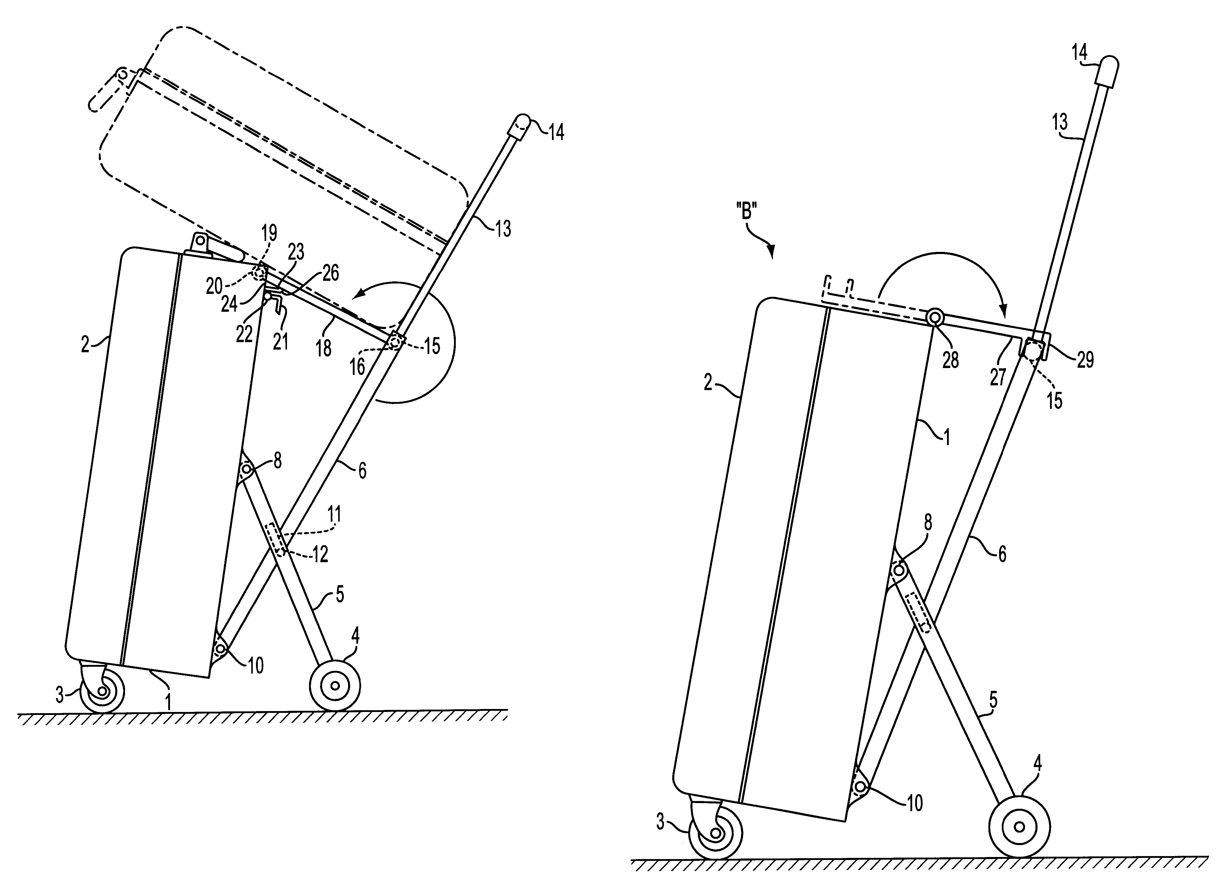
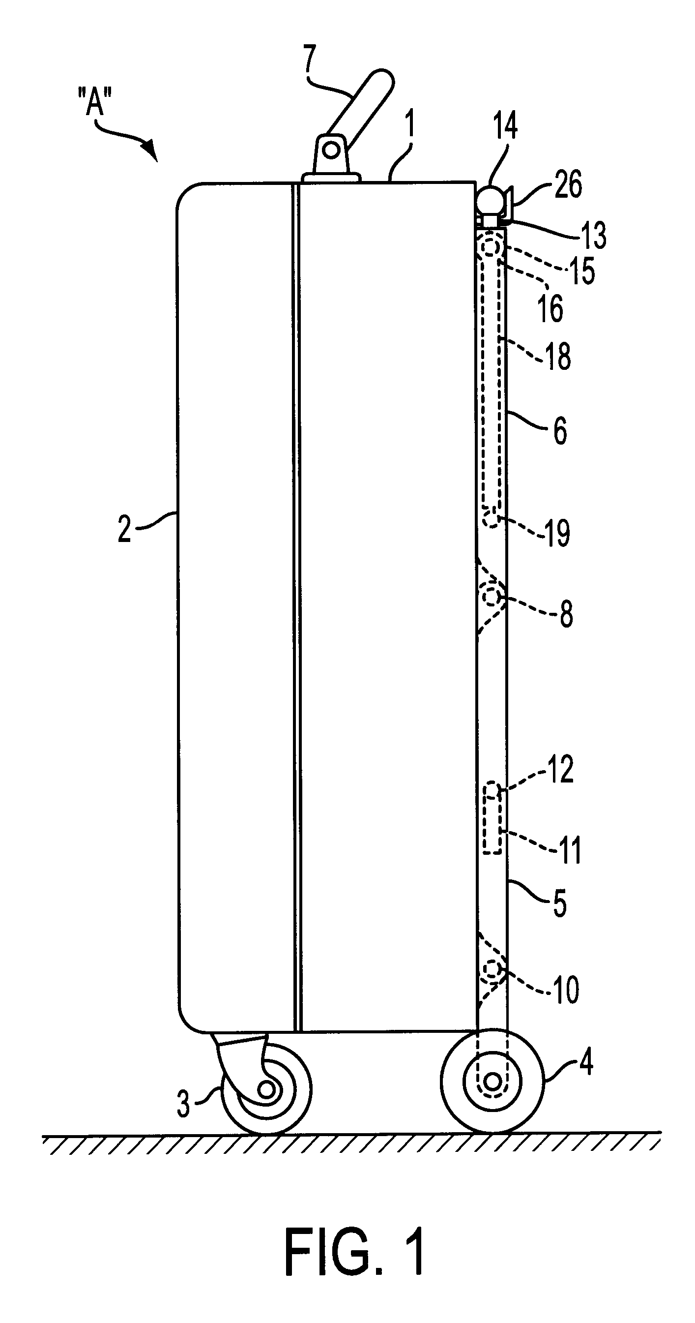
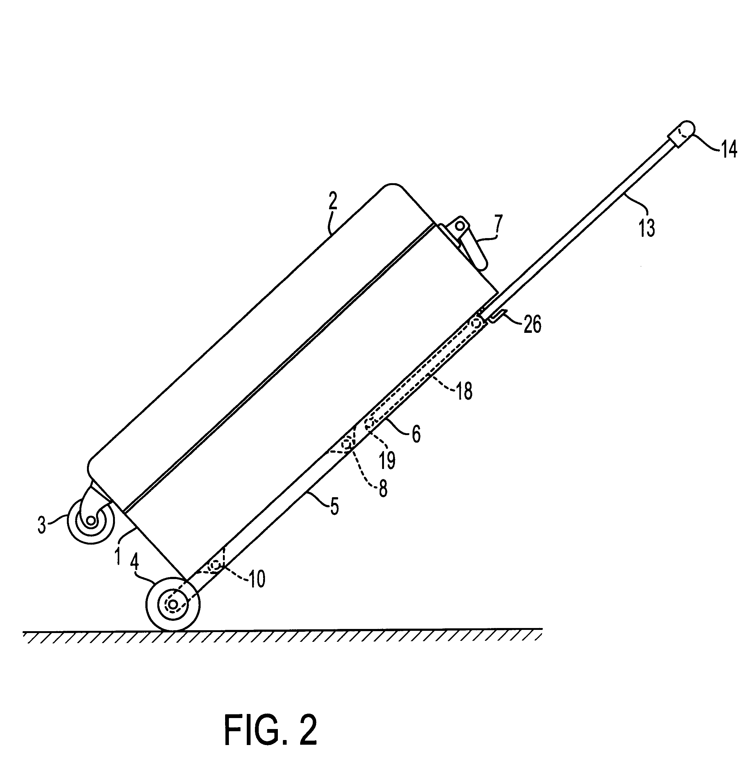
Referring to FIGS. 1 and 4, a multi-purpose traveling luggage "A" comprises a case body 1 (which has an associated case cover 2 in front, and a backboard [number not shown] at the back side), a pair of caster wheels 3, a pair of leg wheels 4, a pair of leg supports 5, a pair of drive rod members 6, and a handle bar 7. When the luggage "A" is in an erect position, the two caster wheels 3 are located at the bottom outer comers of the case cover 2, and the two leg wheels 4 are attached to the lower portions of the two leg supports to form a four-point support for the luggage "A". At this position, the luggage can be lifted and carried by hand through the handle bar 7 on top of the case body 1.

As shown in FIGS. 1 and 4, the leg wheels 4 are rotatably attached to the lower ends of the leg supports 5. The upper ends of the leg supports 5 are fixedly connected to the outer edges of the midportion of the backboard of the case body 1 by a pair of pivot means 8 (such as hinges, bolts, or scre...


PUM


Abstract

The present invention relates to a multi-purpose traveling luggage which comprises a case body with an associated cover at front and a backboard in the back. When the luggage is positioned in an erect position, the outer comers at the bottom of the associated cover has two caster wheels and the lower portion of the backboard is connected to a pair of leg supports. The lower portions of the leg supports comprise a pair of leg wheels, and the upper portions of the leg supports are connected to the outer edges at the midportion of the backboard. There is a pair of drive rod members having their lower portions connected to the lower outer edges of the backboard and their upper portions connected to each other by a connecting rod member. The drive rod members are connected to the leg supports through the engagement of elongated scissor grooves on the leg supports and scissor pins on the drive rod members. Thereby when the drive rod members are in the open position, they form a scissor-like support frame with the leg supports. The drive rod members telescopically receive a pair of extension rods which are united by a handle bar for handling the support frame on the casters and the leg wheels. The two distal ends of the connecting rod member are encased in two casing tubes which can rotate on the connecting rod member pivotally. In the first embodiment, there is provided for a connecting board which is attached to the casing tubes and which can be flipped on top of the case body and be used as a cart for carrying goods. In the second embodiment, there is provided for an article carrying board which at one end is pivotally connected to the top of the backboard and the front end comprises a U-shaped hook. Such a U-shaped hook and be flipped over and locked in onto the connecting rod member so as to form a sturdy structure for carrying goods.

Description

The present invention claims the priority of Taiwanese Patent Application No. 088205734, filed on Apr. 14, 1999, and issued on Jan. 21, 2000, as Taiwanese Patent No. 380388, which is herein incorporated by reference.1. Field of the InventionThe present invention relates to a traveling luggage, especially, a multi-purpose traveling luggage which helps a traveler alleviate troubles due to having multiple luggages. The present invention is an improvement of U.S. Pat. No. 6,016,893, issued on Jan. 25, 2000, which is herein incorporated by reference.2. Background of the InventionIt is usually very inconvenient and burdensome for a traveler to carry numerous luggages. To minimize the inconvenience, various innovations have been developed and sold in the market. Examples of such innovations include using a foldable lightweight stroller to assist in transporting heavy luggages, designing luggages with an attached pulling bar and rolling wheels for easy movement, etc. However, these designs ...

Claims


Application Information

Patent Timeline
IPC IPC(8): A45C13/26A45C13/00A45C5/14A45C5/00B62B1/00B62B1/12B62B3/00B62B3/02B62B3/10
CPCA45C5/14A45C13/262B62B1/125A45C13/385Y10T16/451B62B2202/24B62B2205/04
Inventor CHEN, JOSEPH KUAN-TAN
Owner ISABELITA HILARIO CHEN
Why Eureka
Try Eureka