Vehicle tool tray

a tool tray and vehicle technology, applied in washstands, variable height tables, instruments, etc., can solve the problems of mechanics forgetting where they placed tools, requiring repeated walking and bending, and tools that have a tendency to be jostled and fallen

Inactive Publication Date: 2001-06-05
PASKEY DENNIS J +2
View PDF17 Cites 73 Cited by
  • Summary
  • Abstract
  • Description
  • Claims
  • Application Information

AI Technical Summary

Benefits of technology

It is an object of the invention to provide improved elements and arrangements thereof in an apparatus for the purposes described which is inexpensive, dependable and fully effective in accomplishing its intended purposes.

Problems solved by technology

If the mechanic goes about his work in orderly fashion, he would normally have to make repeated trips back and forth to his tool box and the work bench, requiring repetitious walking and bending beneath the hood.
The problem with such expedients is that invariably the tools have a tendency to become jostled and fall through the engine compartment onto the ground beneath the vehicle, or the mechanic will forget where he placed the tool.
Small parts and fasteners have an annoying proclivity for falling on the engine into locations where they are difficult to see or locate.
Further, some small parts need to be taken out in a particular order and replaced to their exact location, and they invariably become indistinguishably intermixed with such makeshift expedients.

Method used


Image

  • Vehicle tool tray
  • Vehicle tool tray
  • Vehicle tool tray

Examples


Embodiment Construction

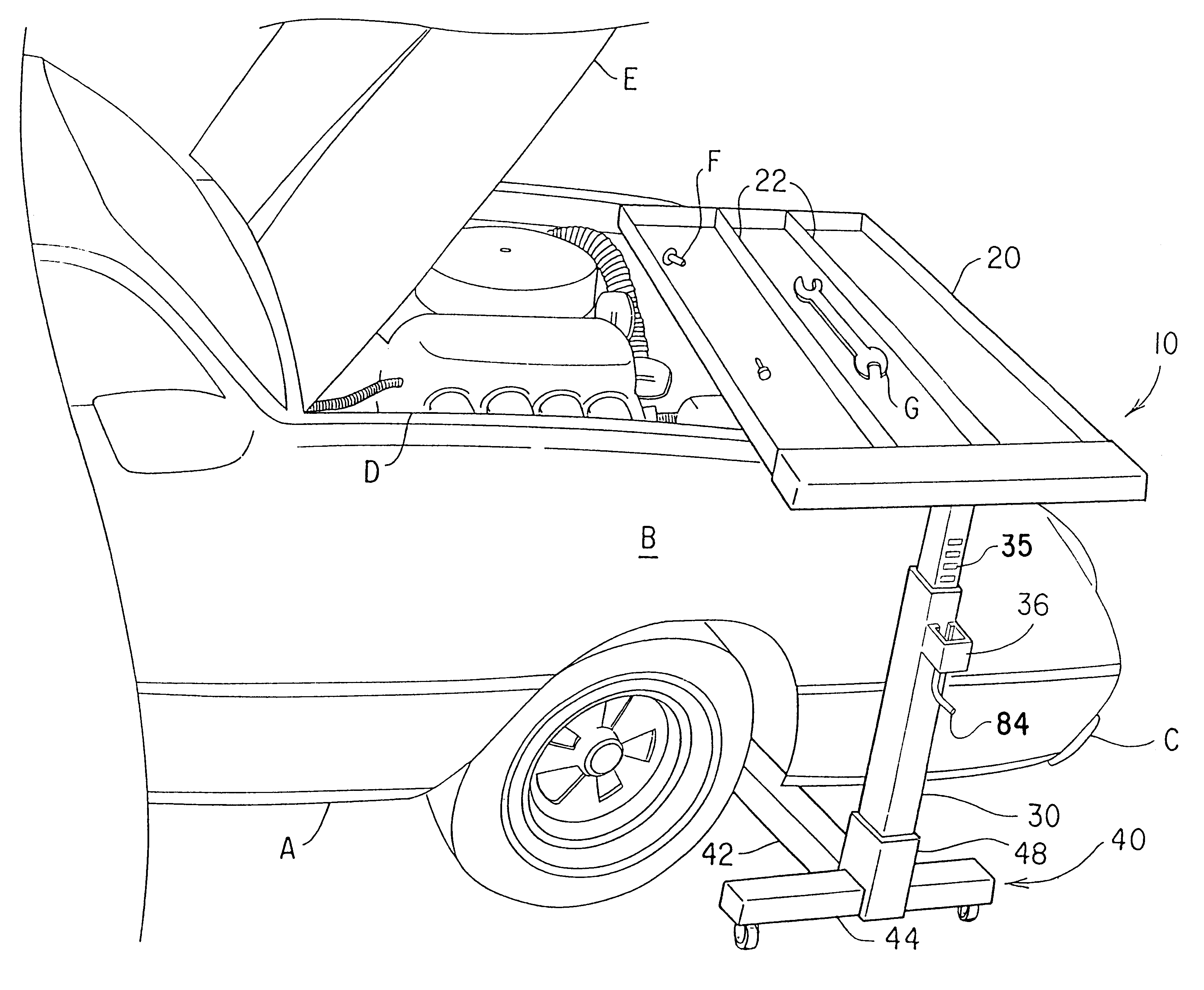
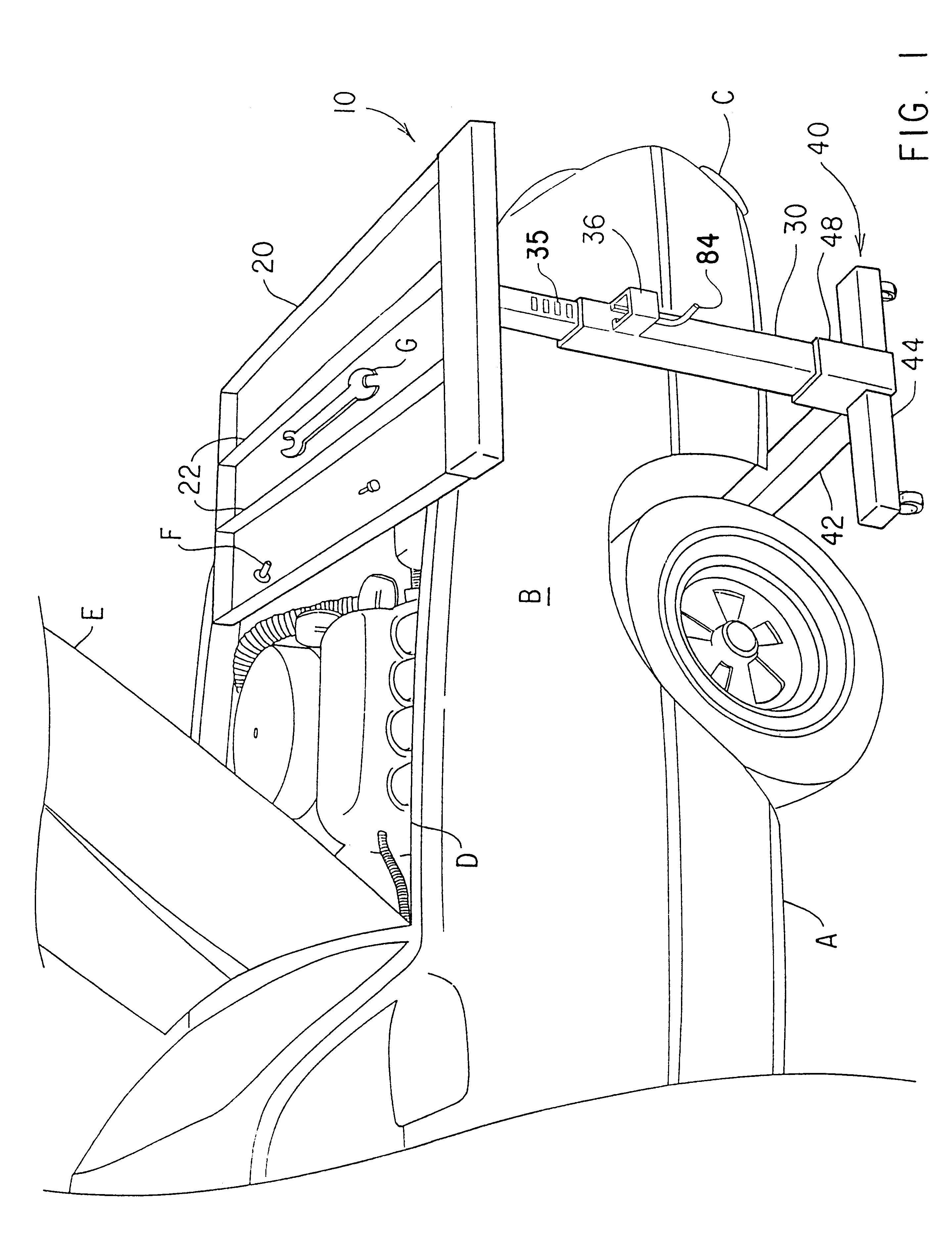
The present invention is a vehicle tool tray, designated generally as 10 in FIGS. 1 through 5. As shown in FIG. 1, the vehicle tool tray 10 includes a tray 20 mounted in cantilever fashion on a vertical post 30 rising from a T-shape base 40. The construction of the device is designed to permit rolling the base 40 under the fender B or bumper C of a vehicle A so that the tray 20 extends over the engine compartment D of the vehicle A with the hood E raised. In a preferred embodiment, the tray 20 is divided into compartments by a plurality of divider walls 22 to provide a conveniently accessible platform for organizing and storing assorted fasteners F and tools G while working on the engine. Alternatively, the tray 20 need not be divided into compartments and may be furnished without divider walls 22, or the divider walls 22 may be removable to provide the user with the option of whether or not to divide the tray into compartments.

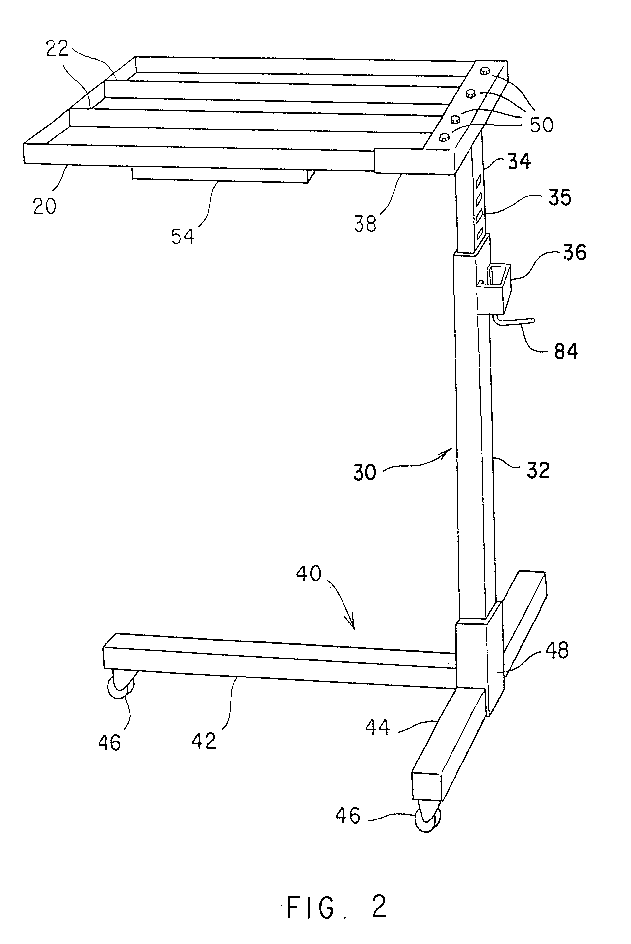
The vehicle tool tray 10 is shown in more detail in FIG...


PUM


Abstract

The vehicle tool tray has a T-shaped based mounted on casters. A vertical post is mounted to the base at the junction of the shaft and crossbar of the Tee. The vertical post is composed of two telescoping sections which are preferably square and tubular in cross section. The telescoping sections are firmly clamped at the desired height by a lock mechanism having a cam and a crank lever pivotally attached to a U-shaped bracket, the cam releasably engaging one of a plurality of slots defined in the upper section of the vertical post. The upper telescoping section of the vertical post is also T-shaped. A pair of short angle irons extend horizontally from the ends of the crossbar of the upper section of the vertical post. The tray is supported on the angle irons and crossbar of the upper section in cantilever fashion. The tray includes a plurality of dividers sectionalizing the top surface of the tray into compartments adapted for holding tools or small parts. The tray includes a drawer mounted on slides on the bottom surface of the tray. The vehicle tool tray is particularly adapted for working on a vehicle with the hood open, the base being wheeled under the vehicle and the tray extending over the engine compartment in cantilever fashion.

Description

BACKGROUND OF THE INVENTION1. Field of the InventionThe present invention relates to tool caddies, and particularly to a vehicle tool tray which may be wheeled to a position under the open hood of a vehicle for the convenience of a mechanic working on the vehicle.2. Description of Related ArtThe automobile mechanic is frequently required to open the hood of the vehicle and work on the engine. In the course of diagnosing engine problems or making repairs, he may have occasion to use a variety of tools and to remove small parts and fasteners. The task at hand may require that he set one or more tools aside in order to have one or both hands free for manipulation of various components under the hood. If the mechanic goes about his work in orderly fashion, he would normally have to make repeated trips back and forth to his tool box and the work bench, requiring repetitious walking and bending beneath the hood.Frequently, the mechanic will resort to various improvisations and expedients ...

Claims


Application Information

Patent Timeline
Patent Type & Authority Patents(United States)
IPC IPC(8): B25H1/00B25H5/00B25H1/16B25H1/12
CPCB25H1/12B25H1/16B25H5/00
Inventor PASKEY, DENNIS J.BOOTH, D. JAMESBOOTH, MICHAEL J.
Owner PASKEY DENNIS J
Why Eureka
Try Eureka