Vertical axis wind turbine

Inactive Publication Date: 2001-06-05
SMEDLEY RONALD H
View PDF21 Cites 82 Cited by
  • Summary
  • Abstract
  • Description
  • Claims
  • Application Information

AI Technical Summary

Problems solved by technology

Most wind turbines are subject to possible damage from excessively high winds.
However, high winds can damage vertical axis tur

Method used


Image

  • Vertical axis wind turbine
  • Vertical axis wind turbine
  • Vertical axis wind turbine

Examples


Embodiment Construction

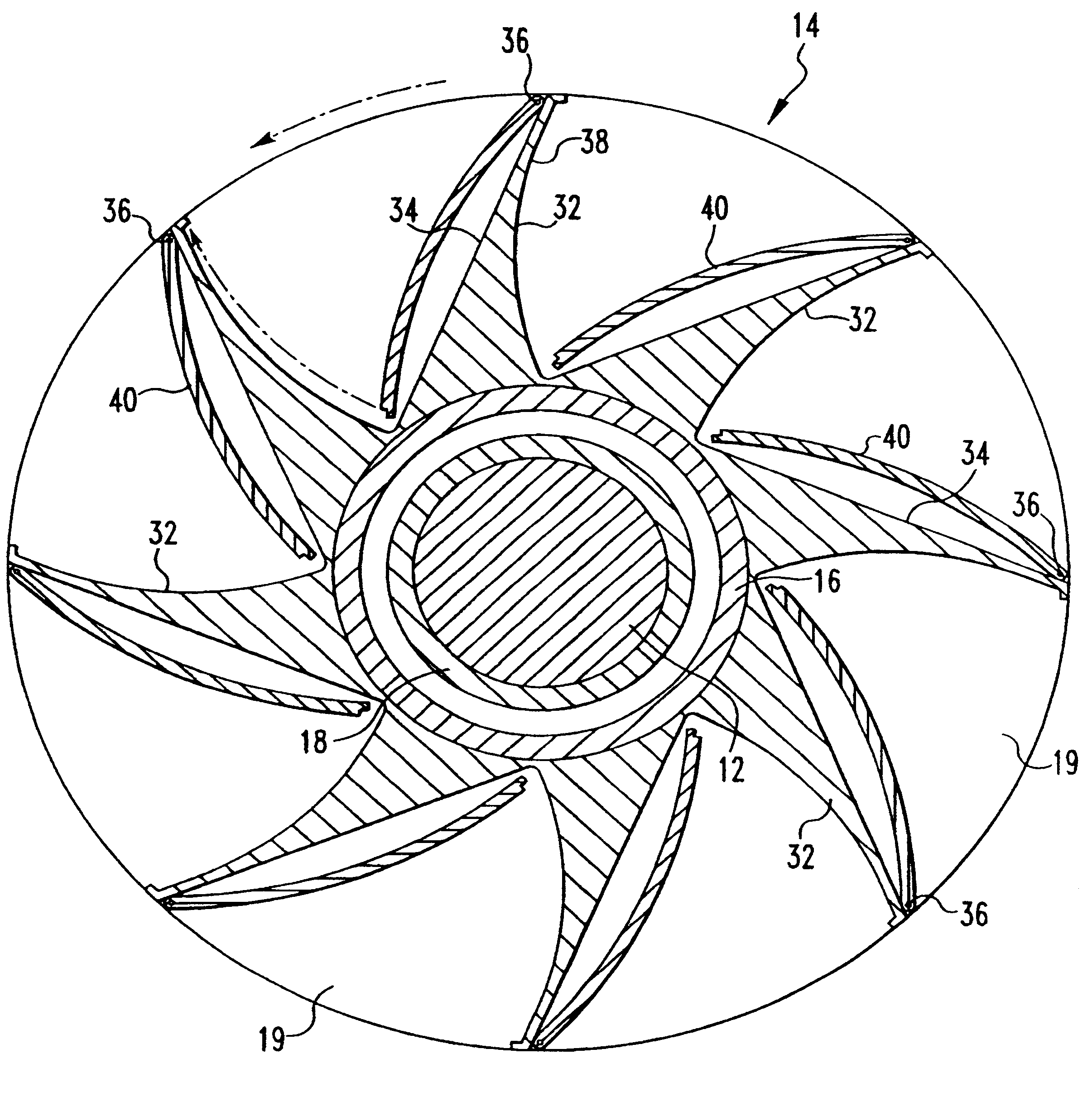
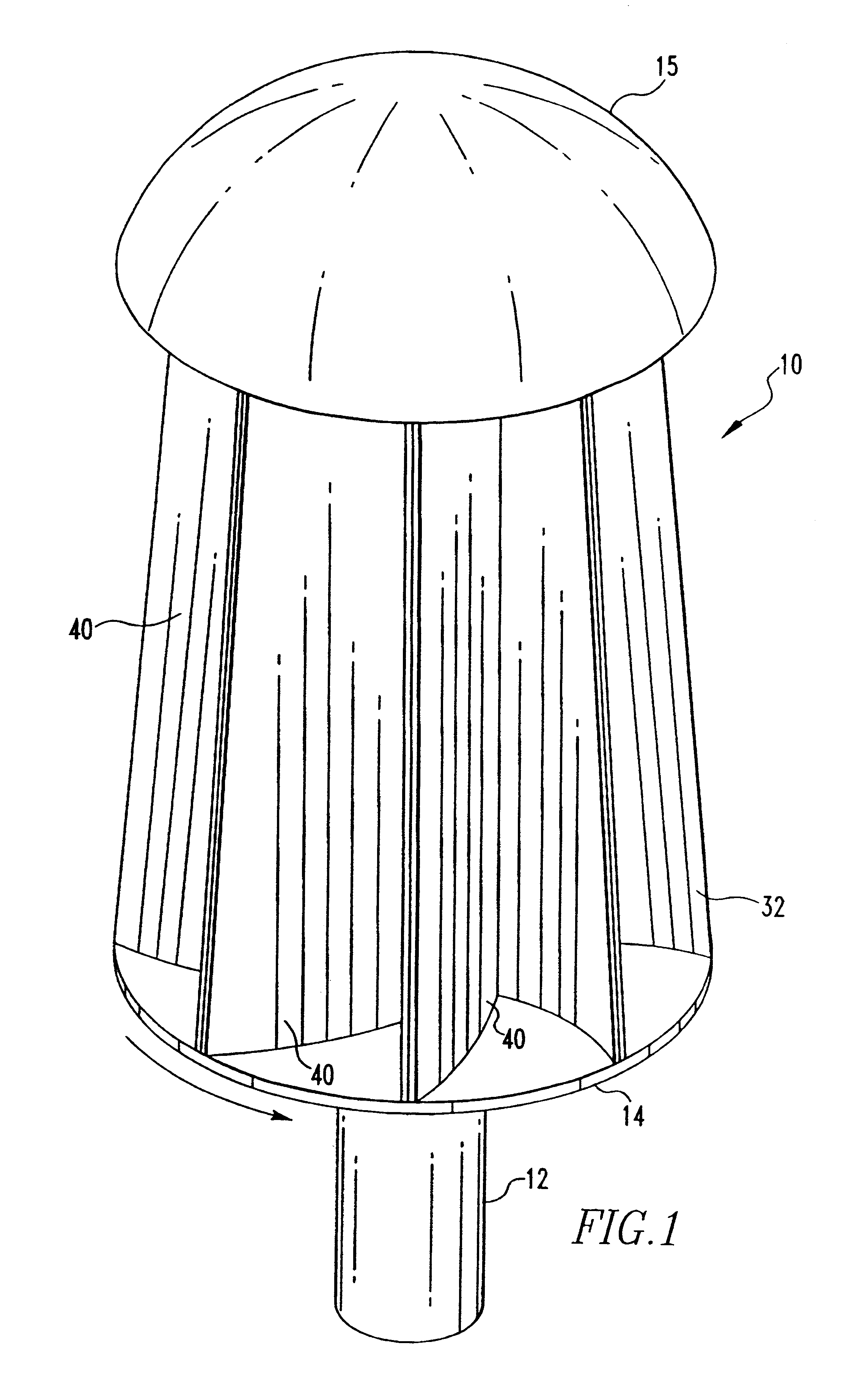
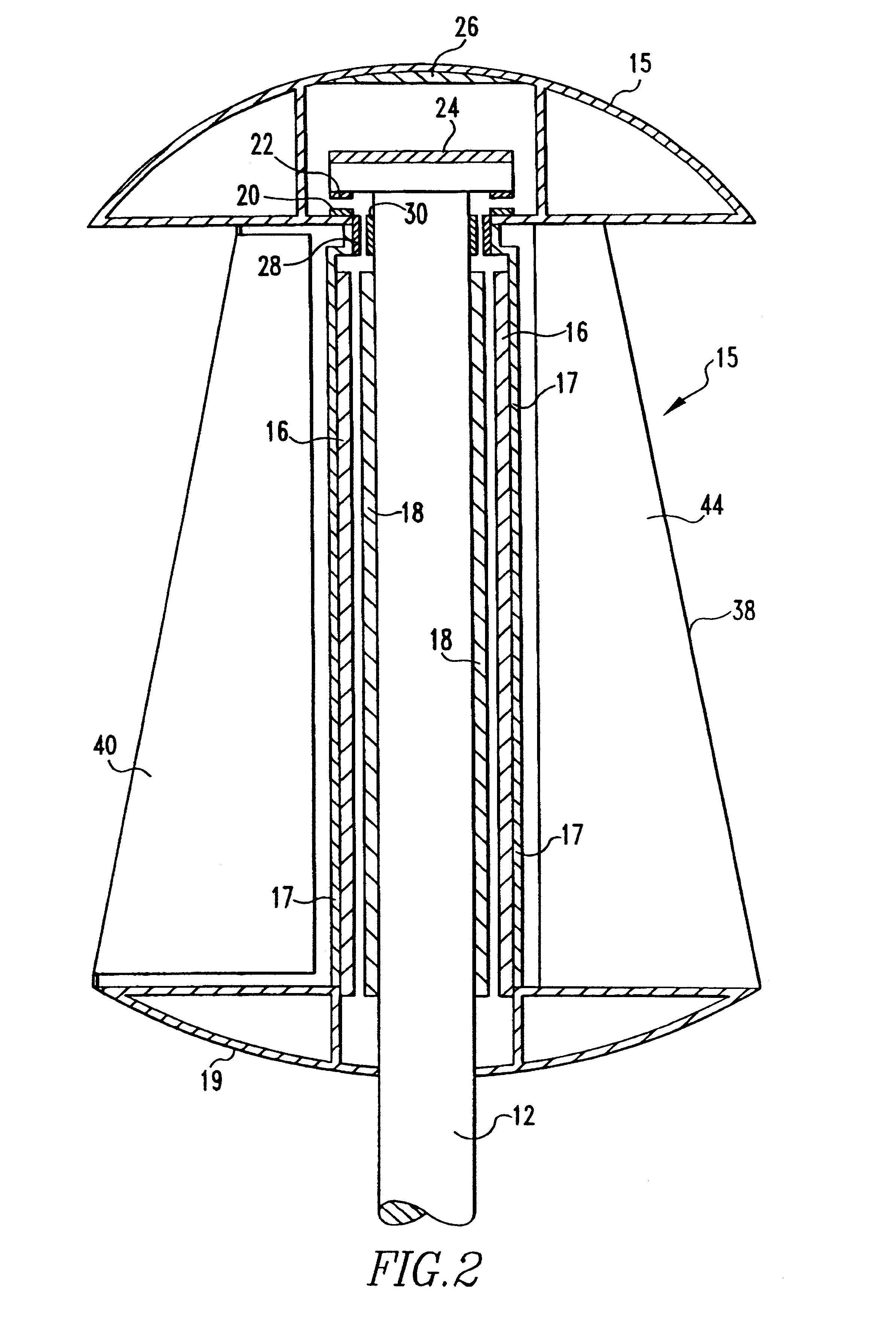
FIG. 1 shows a preferred embodiment of a wind turbine 10 of this invention as including a support column 12, a rotor 14 on the column, and a cap 15 on the rotor and support column. In the preferred embodiment, the column 12 is stationary or non-rotating, and the rotor 14 rotates or turns on the stationary column. This embodiment includes coils 16 and 18 (FIGS. 2 and 3), for generating electrical power as the rotor 14 turns. As an alternative, the rotor could be fixedly secured to the support column and turn the column, which would drive a separate generator at the base of the column. In the embodiment of FIG. 1, the support column 12 is securely mounted on a base, not shown, to hold the turbine 10 in position. The base can either be on the ground or secured to the top of another structure such as a building or tower.

As shown in FIG. 2, the rotor 14 includes an inner cylindrical liner 17, a disc-shaped base 19 with an open center for the column 12, and a top cap 15 that covers the ro...


PUM


Abstract

A vertical axis wind turbine having a plurality of blades around its periphery and a pivotable door associated with each blade. Each door has a pivot axis that is inclined outwardly toward the bottom of the turbine so that gravitational forces will pull the doors toward an open position. The doors are designed to move toward a closed position to at least partially block wind forces from the blades when the rotor rotates at potentially damaging speeds. The turbine has mating coils on the rotor and the support column to generate electrical energy when the rotor rotates.

Description

1. Field of the InventionThis invention relates to wind turbines for generating electrical power, particularly to vertical axis wind turbines, and more particularly to such turbines having means for preventing catastrophic failures in high winds.2. Brief Description of the Prior ArtWind Turbines provide a source of electrical power as an alternative to fossil fuels to help reduce gaseous emissions and other environmental problems. Wind turbines also provide electrical power in remote areas where power lines have not been strung. Accordingly, numerous wind turbines have been installed in high wind areas in the United States and other countries.Wind turbines have either horizontal axes or vertical axes of rotation, with each type having different advantages and disadvantages. Vertical axis turbines have, among other advantages, little or no need for a tower on which to mount the turbines. The turbine, gearing electrical generators and the like can generally be mounted at ground level....

Claims


Application Information

Patent Timeline
IPC IPC(8): F03D7/06F03D3/06F03D7/00F03D3/00
CPCF03D3/065F03D7/06F05B2240/202F05B2240/215F05B2240/313F05B2240/40F05B2270/1011Y02E10/74F03D3/062
Inventor SMEDLEY, RONALD H.
Owner SMEDLEY RONALD H
Why Eureka
Try Eureka