
Vertical axis wind turbine with wingletted cam-tiltable blades

a technology of vertical axis wind turbine and camtiltable blade, which is applied in the direction of rotors, greenhouse gas reduction, vessel construction, etc., can solve the problems of difficult maintenance, large towers, and difficult maintenance, and achieve the effect of optimum power and easy setting

Inactive Publication Date: 2009-02-05
SEVEN STARS WORLDWIDE
View PDF5 Cites 43 Cited by
  • Summary
  • Abstract
  • Description
  • Claims
  • Application Information

AI Technical Summary

Benefits of technology

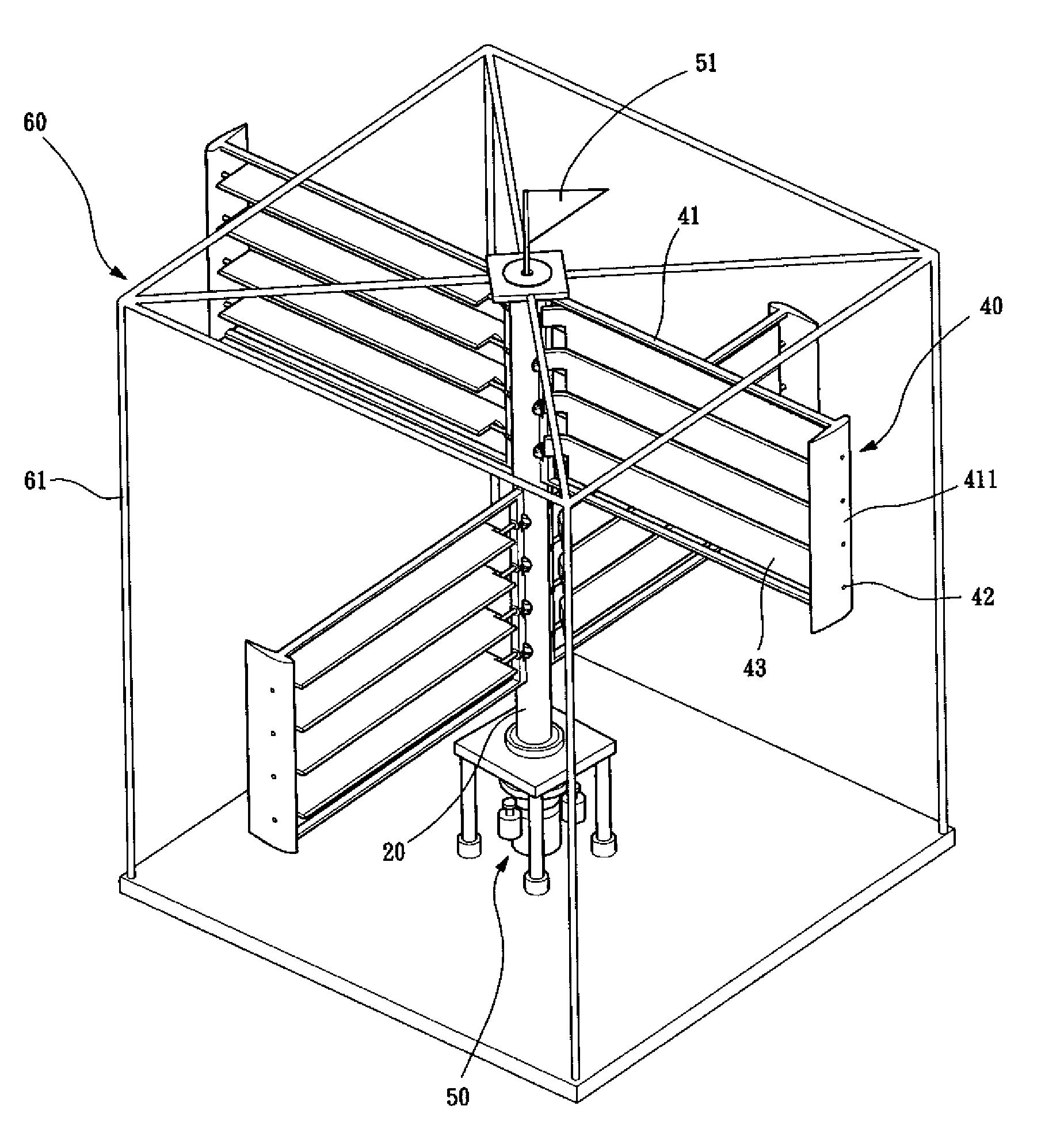
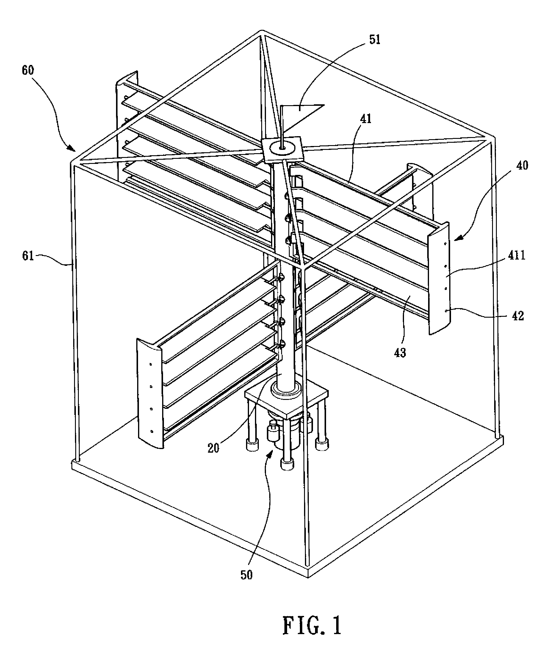
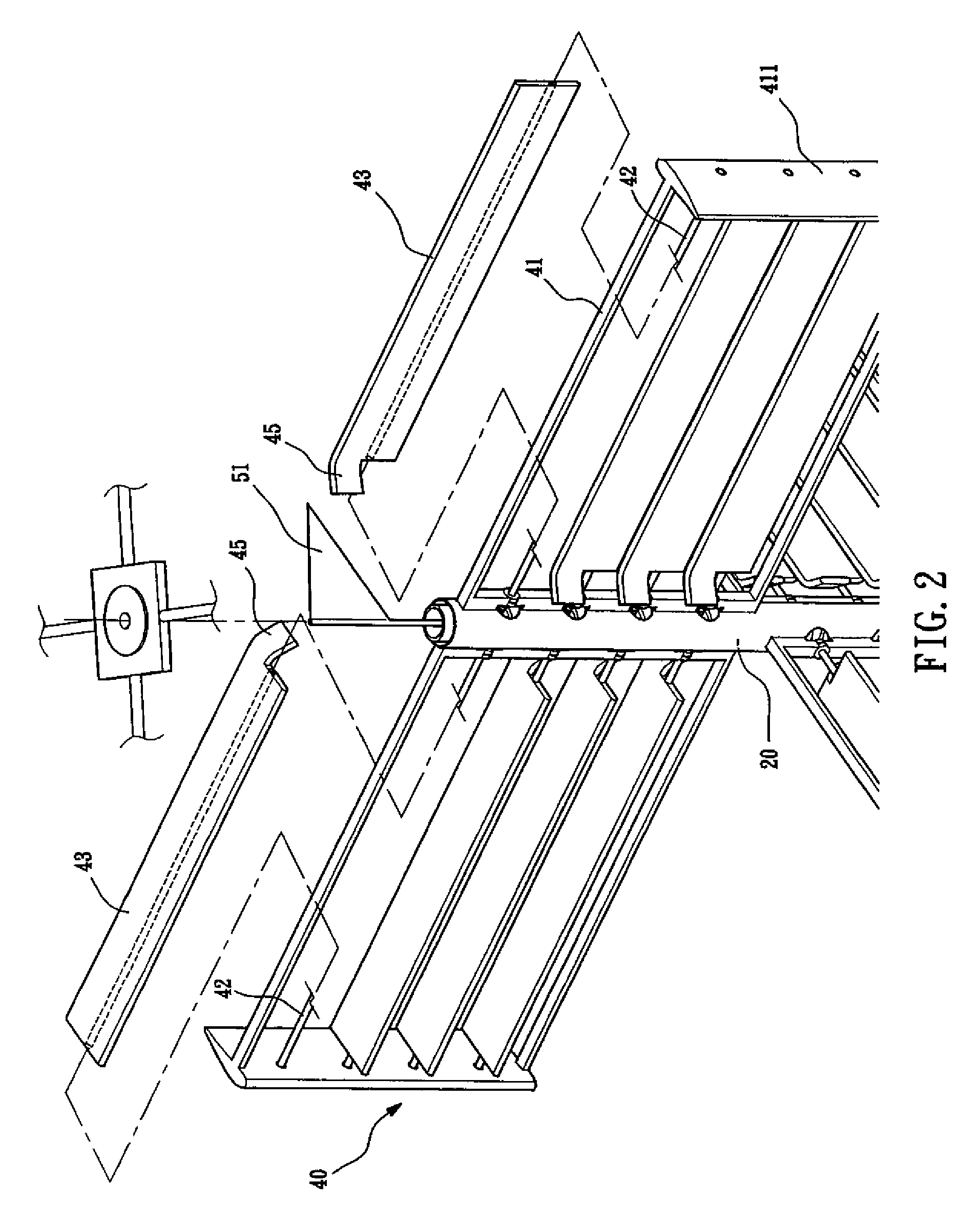
[0022]In accordance with the present invention, a vertical axis wind turbine with wingletted cam-tiltable blades is provided, comprising: a generator, a shaft interconnected with the generator, and a plurality of blade sets coupled to the shaft. Cam members are provided inside the shaft and have guide sections of pre-determined shapes. A blade set includes blades that are coupled to crank arms in contact with the guide sections. Thus, when the blades are located in a windward position and a leeward position respectively, the blades are caused by the guide sections to automatically and easily set in an optimum pressure-receiving condition and a least wind-resistance condition, respectively, for receiving wind energy from variable directions, so that the shaft is rotatable even with low wind speeds to achieve optimum power.

Problems solved by technology

Due to the increasing consumption of fossil fuel, reserves of fossil fuel are gradually getting depleted and increasing levels of carbon dioxide are causing a severe “greenhouse” phenomenon in the Earth's atmosphere.
This makes the tower very bulky, costly and difficult to maintain.
Thus, the known construction of the horizontal axis wind turbine is apparently not an ideal solution for wind power stations.
(1) The construction is complicated and assembly is difficult, both leading to increased costs;
(3) The design of the structure is poor because a huge initial driving force is needed to swivel the blades to face the wind direction, such that the blades cannot be properly swiveled in low wind speed conditions, leading to low power generation efficiency.
Other prior references are also known, including U.S. Pat. Nos. 3,995,170; 6,688,842; and 6,749,394, none of which discloses effective use of the aerodynamic force, and all of which have the following drawbacks:
(1) All the blades are individually arranged in a vertical state, and are not interconnected to facilitate swiveling thereof (the blades of U.S. Pat. No. 3,995,170 are interconnected, but a transmission mechanism is needed for the interconnection), so that the initial driving force for swiveling the blades is huge;
(2) The blades have to be swiveled (by an angle of as much as 180 degrees) to face the wind direction by a huge initial driving force so that the blades cannot be swiveled in low wind speed conditions, leading to poor power generation efficiency; and
(3) The blades are not of a design or construction good enough to facilitate swiveling of the blades with a small initial driving force.
(1) The construction is complicated and assembly is difficult, both leading to an increase of costs; and
(2) The swiveling of the blades is driven by mechanical transmission, so that the initial driving force for swiveling the blades is huge and the blades cannot be swiveled in low wind speed conditions, leading to poor power generation efficiency.
Further references, such as Chinese Patent No. 96120092.8, disclose a blade swiveling system that uses a wind vane to track the wind direction and issue an electronic signal to control a servo motor which swivels the blades, but the blades have to be driven all the way by the servo motor, leading to consumption of electrical power and increased risk of breakdown caused by undesired influences of temperature and / or humidity on the electronic components.
In addition, the motor is mounted on a rotary member and a rotary joint has to be established to transmit electrical power, leading to high risk of failure.
(1) A huge initial driving force is needed for tilting or swiveling the blades to face the direction of the incoming air flows, and tilting or swiveling the blades is generally impossible in low wind speed conditions, such that the efficiency of power generation is quite low.
(2) The design of the blades is poor, including using additional winglets to facilitate the tilting or swiveling of the blades, such that a huge initial driving force is needed for swiveling the blades.

Method used


Image

  • Vertical axis wind turbine with wingletted cam-tiltable blades
  • Vertical axis wind turbine with wingletted cam-tiltable blades
  • Vertical axis wind turbine with wingletted cam-tiltable blades

Examples


Embodiment Construction

[0039]The following descriptions are of exemplary embodiments only, and are not intended to limit the scope, applicability or configuration of the invention in any way. Rather, the following description provides a convenient illustration for implementing exemplary embodiments of the invention. Various changes to the described embodiments may be made in the function and arrangement of the elements described without departing from the scope of the invention as set forth in the appended claims.

[0040]With reference to the drawings and in particular to FIGS. 1-6, a vertical axis wind turbine constructed in accordance with the present invention comprises a generator 10, a shaft 20, a first cam member 31, a second cam member 32, a plurality of blade sets 40, a cam driver device 50, and a support frame 60. The blade set 40 comprises blades 43 each coupled to a crank arm 44 that is engaged to guide sections 311, 321 of the first and second cam members 31, 32. When the blades 43 are in a wind...


PUM


Abstract

A vertical axis wind turbine with wingletted cam-tiltable blades is provided, including: a generator, a shaft interconnected with the generator, and a plurality of blade sets coupled to the shaft. Cam members are provided inside the shaft and have guide sections of predetermined shapes. The blade set includes blades that are coupled to crank arms in contact with the guide sections. Thus, when the blades are located in a windward position and a leeward position respectively, the blades are caused by the guide sections to automatically and easily set at an optimum pressure-receiving condition and a least wind-resistance condition respectively, for receiving wind energy from variable directions so that the shaft can be rotated in low wind speed conditions to drive the generator for power generation.

Description

BACKGROUND OF THE INVENTION[0001]1. Field of the Invention[0002]The present invention relates to a vertical axis wind turbine with wingletted cam-tiltable blades, and in particular to a vertical axis wind turbine that employs a guide means constituted of cams and crank arms, and aerodynamic force, to control the tilting or swiveling of the angle of the blades, such that is the blades are automatically set in a windward position to receive wind energy from variable directions so as to cause the shaft to drive a power generator even in low wind speed conditions and thereby realize optimum power generation performance.[0003]2. The Related Arts[0004]Due to the increasing consumption of fossil fuel, reserves of fossil fuel are gradually getting depleted and increasing levels of carbon dioxide are causing a severe “greenhouse” phenomenon in the Earth's atmosphere. Thus, the United Nations has issued regulations and commands and is coordinating the fight against global warming. Recently, m...

Claims


Application Information

Patent Timeline
IPC IPC(8): F03D7/06
CPCF03D3/068Y02E10/74F05B2260/79F05B2260/75
Inventor KUO, WEN-CHUNGHSIAO, TING-HAOCHAO, YU-LANHU, CHIA-NANGRIFFIN, MARK WILLIAM
Owner SEVEN STARS WORLDWIDE
Learn More