
Vertical axis wind turbine system

a vertical axis wind turbine and wind power technology, applied in the direction of propellers, propulsive elements, water-acting propulsive elements, etc., can solve the problems of reducing creating a safety hazard, and reluctance to have them installed, so as to increase the efficiency of the vertical axis wind turbine and increase the amount of electrical power

Inactive Publication Date: 2008-06-19
SRI VAWT
View PDF5 Cites 41 Cited by
  • Summary
  • Abstract
  • Description
  • Claims
  • Application Information

AI Technical Summary

Benefits of technology

[0013]A second object of the present invention is to present a more efficient vertical axis wind turbine that supplies an increased amount of electrical power.
[0014]A third object of the present invention is to make known a novel turbine mast that increases efficiency of the vertical axis wind turbine of the present invention.

Problems solved by technology

There are several common problems associated with HAWT machines.
The more powerful horizontal axis turbines have long blades that require accurate placement out of the way of both natural and man-made obstructions and can create a safety hazard.
They generate significant noise so as to cause some reluctance to have them installed near populated areas.
These opposing high and low torque conditions can produce torsion on the bearings and support towers.
However, VAWTs do have drawbacks.
This occurs because of the lift and drag produced by the turbine as it spins.
The necessity of using additional starting devices reduces the efficiency of the Darrieus type of vertical wind turbine.
Thus, there exists in the field the problems of reducing the pulsating effect found in the rotation of vertical axis turbines and increasing the efficiency of vertical axis turbines.

Method used


Image

  • Vertical axis wind turbine system
  • Vertical axis wind turbine system
  • Vertical axis wind turbine system

Examples


Embodiment Construction

[0032]At the outset, it should be appreciated that like drawing numbers on different drawing views identify identical structural elements of the invention.

[0033]While the present invention is described with respect to what is presently considered to be the preferred embodiments, it is understood that the invention is not limited to the disclosed embodiments. The present invention is intended to cover various modifications and equivalent arrangements included within the spirit and scope of the appended claims.

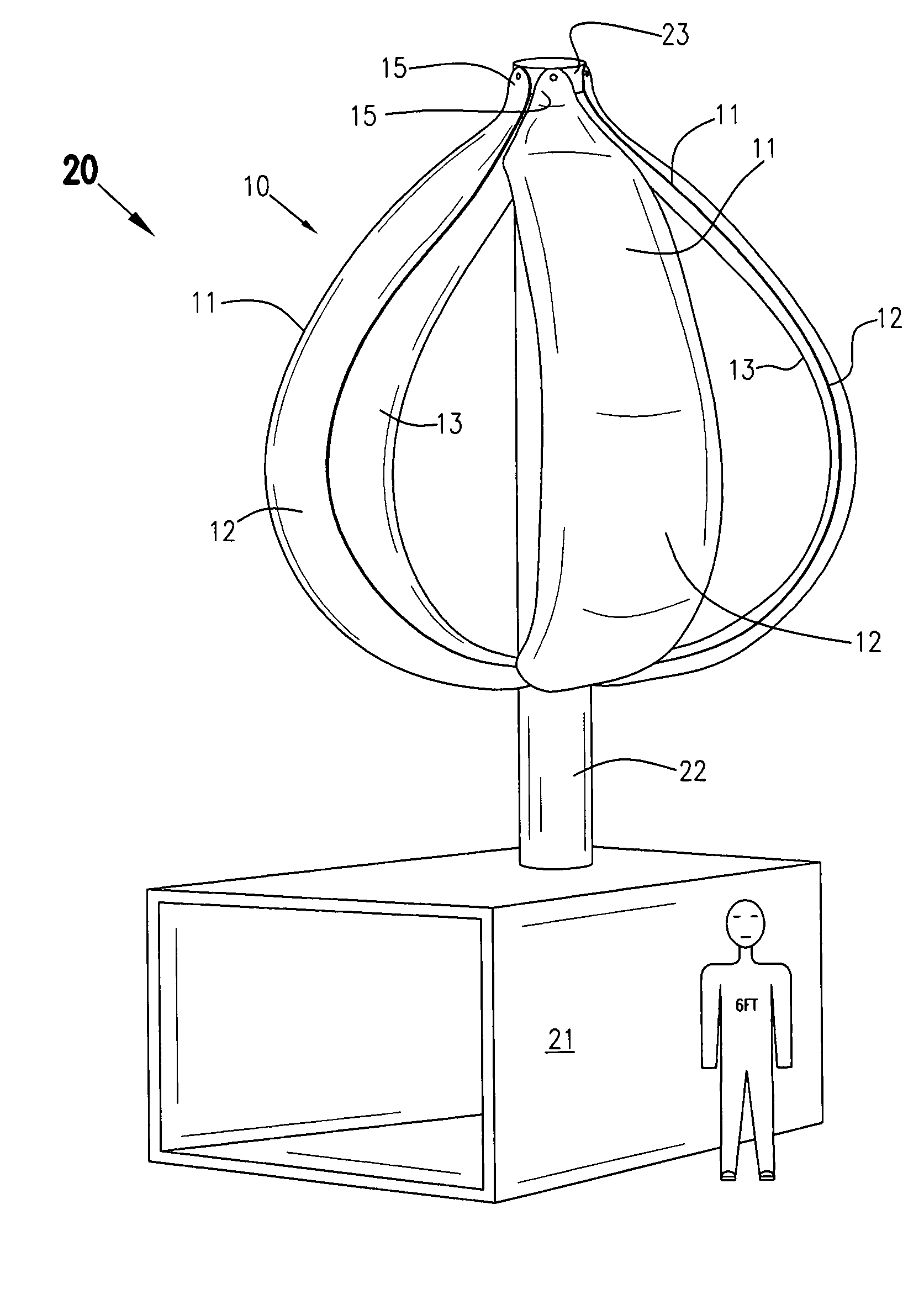
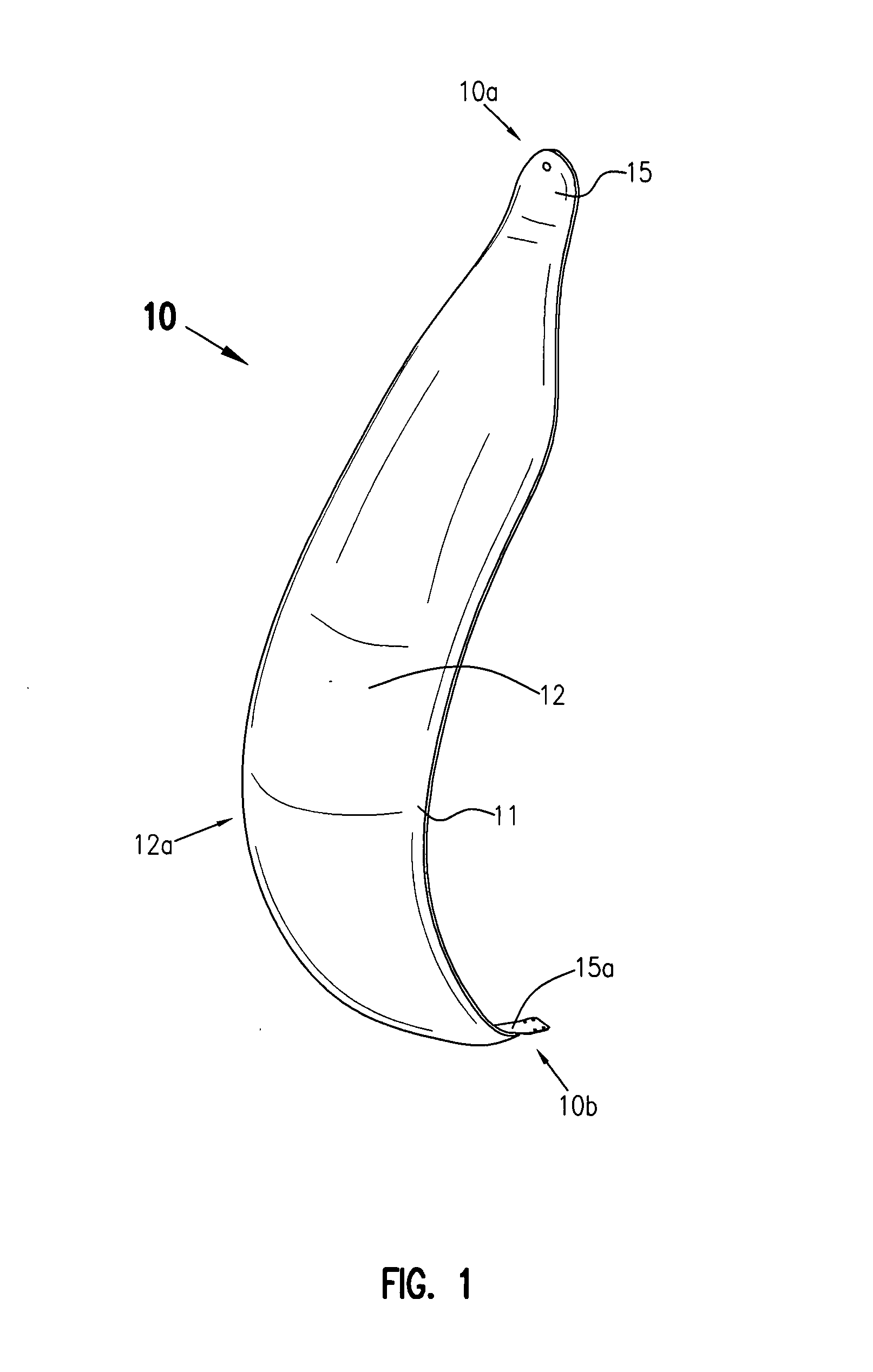
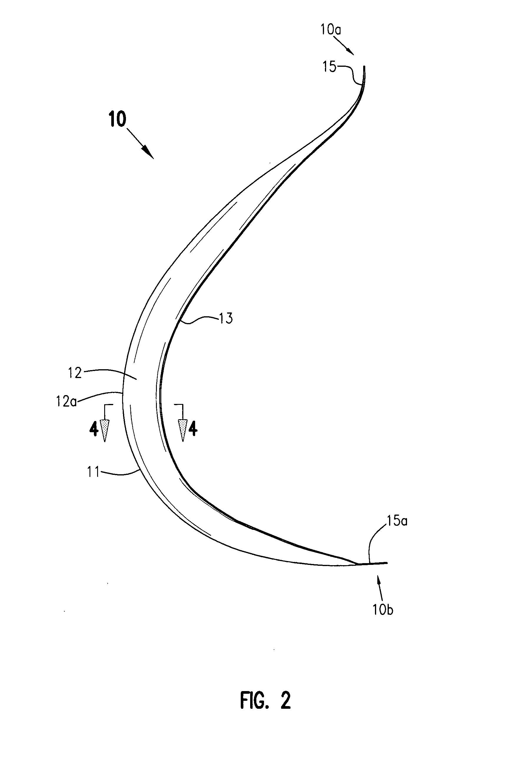
[0034]Adverting to the drawings, FIG. 1 depicts a perspective view of the outer facing or surface of turbine blade 10 (“blade 10”) of the present invention. Blade 10 is a modified 27-2012 airfoil formed into a curve with a smaller radius of curvature than the prior art 27-2012 airfoil. In one embodiment, blade 10 comprises tapered first end 10a having an endpiece 15 that is flexible to allow twisting of blade 10 and tapered second end 10b with an endpiece 15a. Endpieces 15 and 1...


PUM


Abstract

The present invention is a vertical wind turbine having a turbine with a plurality of blades or wind vanes. The blades are constructed and attached to the shaft of the turbine so as to allow them to twist open to present more surface area to wind currents when a threshold rotational velocity is reached. Also presented are a novel outer shell that is placed over at least part of the shaft and a novel turbine blade.

Description

CROSS REFERENCE TO RELATED PATENT APPLICATION[0001]This application claims the benefit under 35 U.S.C. §119(e) of U.S. Provisional Application No. 60 / 836,526, filed Aug. 9, 2006.FIELD OF INVENTION[0002]This application is generally related to the field of energy-generating wind turbines, more specifically to vertical axis wind turbines, and still more particularly to the incorporation of novel turbine blade in a vertical axis wind turbine.BACKGROUND OF THE INVENTION[0003]Because of the steady depletion of easily obtainable carbon based fuels, such as petroleum and coal, there is an accelerating search for non-carbon based and renewable energy sources. One such renewable energy resource is wind power. Over centuries many types of devices designed to harness blowing wind to generate mechanical energy or, more recently, electrical energy have been developed. The famous windmills of the Netherlands and elsewhere have been and still are used for milling grain and pumping water out of low...

Claims


Application Information

Patent Timeline
IPC IPC(8): F03D3/00F03D11/00F01D5/14
CPCF03D3/005F03D7/06Y02E10/74F05B2240/311F05B2240/313F05B2240/212
Inventor MITCHELL, JOHN SINCLAIRSCOTT, GEORGE ARTHURDETENBECK, MICHAEL JAMES
Owner SRI VAWT
Learn More