Air brakes for trucks

a technology for air brakes and trucks, applied in the direction of actuators, brake types, brake actuating mechanisms, etc., can solve the problems of ratcheting taking up slack, reducing the efficiency of compressors, and still having the needed stoke of brakes

Inactive Publication Date: 2001-07-03
HUNTER MARC
View PDF15 Cites 12 Cited by
  • Summary
  • Abstract
  • Description
  • Claims
  • Application Information

AI Technical Summary

Benefits of technology

The present pneumatic braking system actuates the shoes with pneumatic cylinders, and is an improveme

Problems solved by technology

If it were to fail, the air brake would still have the needed stoke to bring the vehicle to a stop.
If this was the case, the ratchet would take-up slack, alleviating the compressor from running unnecessarily.
If t

Method used


Image

  • Air brakes for trucks
  • Air brakes for trucks
  • Air brakes for trucks

Examples


Embodiment Construction

(i) Description of FIG. 1 and FIG. 2

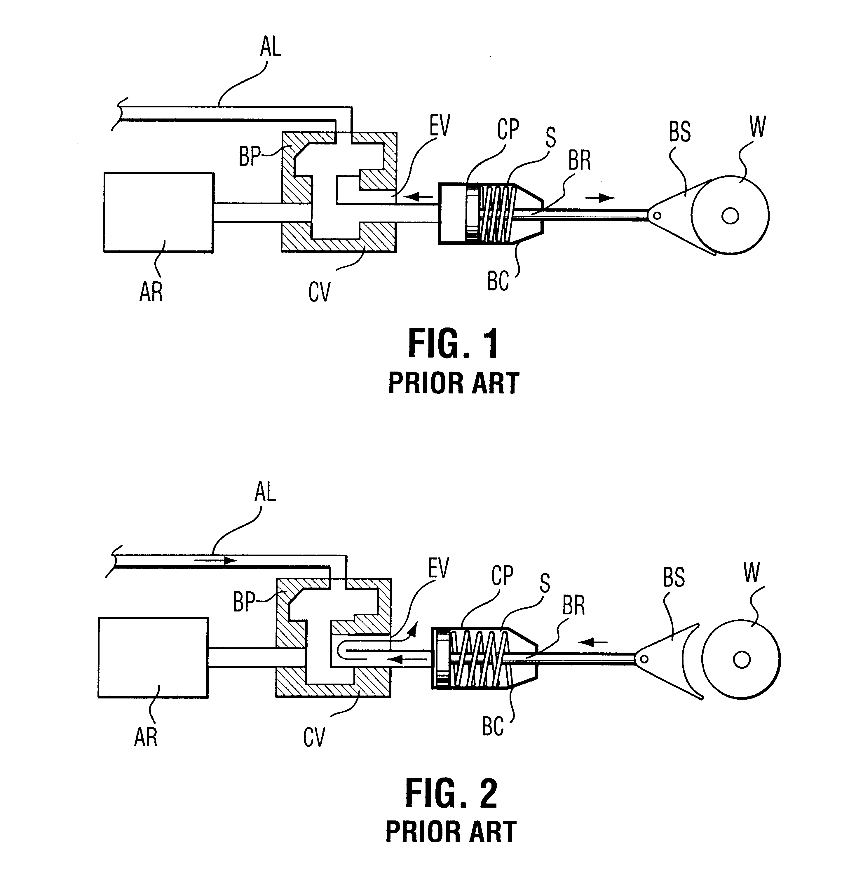
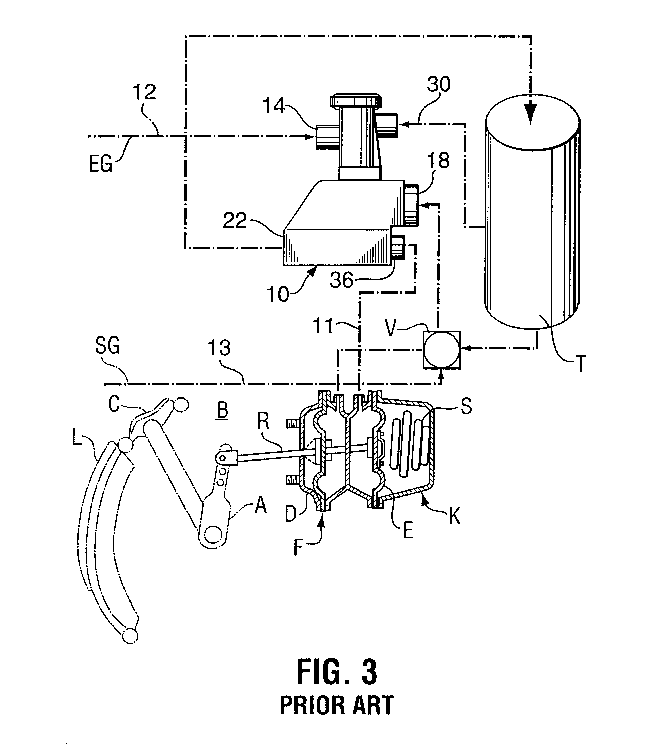
Before describing embodiments of this invention, a brief description of a typical air brake and its operation will be given. As seen in FIG. 1 and FIG. 2, a typical air brake includes an auxiliary reservoir (AR) containing compressed air which is connected to a central valve including an operable / closable compressed air by-pass (BP) and operable / closable exhaust vent (EX). The central valve (CV) is connected to a spring-loaded, brake cylinder (BC) containing a cylinder piston (CP), which is connected to a brake rod (BR) and operating against spring (S). The brake rod (BR) is connected to a brake shoe (BS) which is urged to engage the wheel (W). The central valve (CV) is connected to a principal source of compressed air by a compressed air line (AL).

FIG. 1 shows the brake "applied" position, while FIG. 2 shows the brake "released" position.

As seen in FIG. 1 and FIG. 2, the operation of these conventional air brakes is as follows. To apply the brake...


PUM


Abstract

The present invention provides an improvement in an actuator system for use with a brake system of the type including a brake and a source of compressed air which is connected to an air chamber including a push rod for moving a transverse brake actuator bar between a brake applied position and a brake released position. The push rod operates the transverse brake actuator bar. The actuator system includes an asymmetric operator member which is relatively-rotatably-attached to a non-rotatable wheel support, and which is concentrically-disposed around an axle of a wheel. The asymmetric operator member includes an ear which is attached to the transverse brake actuator bar. A brake arm assembly includes a pair of diametrically-opposed arcuate brake arms, each brake arm including an inner arcuate channel member, one end of the arcuate channel member terminating in a hollow cylindrical bushing, the other end of the channel member terminating in a pair of transversely-spaced-apart ears having aligned apertures therethrough. An inner anchor plate and an outer anchor plate sandwich the asymmetric operator member therebetween and also are relatively-rotatably-attached to the non-rotatable wheel support which is concentrically-disposed around the axle of the wheel. The anchor plates are non-rotatably-secured to the asymmetric operator member. A first bifurcated link is rotatably-attached between the ears of a first channel member and the anchor plates, and a second bifurcated link is rotatably-attached between the ears of a second channel member and the anchor plates. A first hollow cylindrical bushing is rotatably-attached to the anchor plates opposite to the attachment of the second bifurcated link, and a second hollow cylindrical bushing is rotatably-attached to the anchor plates opposite to the attachment of the first bifurcated link. On activating the air pot, the push rod moves the transverse actuator bar to rotate the asymmetric operator member in a counter-clockwise direction, to urge the arcuate brake arm to move in a braking action radially-outwardly from an inactive position towards, and frictionally-engaging, radially-inwardly-facing brake pads, and on venting compressed air from the air pot, the push rod moves the transverse actuator bar to rotate the asymmetric operator member in a clockwise direction, to urge the arcuate brake arms to move in a brake releasing action radially-inwardly to inactive positions away from, and out of frictional engagement with, the radially-inwardly-facing brake pads.

Description

(i) Related InventionThis invention is an improvement on U.S. Pat. No. 5,865,277, patented Feb. 2, 1999, by Marc Hunter, the entire contents of which are incorporated herein by reference.(ii) Field of the InventionThis invention relates to a brake system and brake actuator system for trucks. In one embodiment, it is particularly concerned with pneumatic air braking systems which are used on large trucks which are used in the forestry trucking industry.(iii) Description of the Prior ArtDrum brakes are known to have certain advantages over disc brakes. Those advantages include superior braking force in some situations, and, the continued application of braking force where temperature variations occur while the brake is on.A problem, however, with prior art drum brake assemblies was that they were of complex construction and assembly, and they were generally comprised of a large number of components and parts. Such a large number of parts resulted in the brake assembly being expensive,...

Claims


Application Information

Patent Timeline
IPC IPC(8): F16D65/22F16D65/16F16D65/14F16D51/00F16D51/28
CPCF16D51/28F16D65/22F16D2125/30F16D2125/26F16D2121/02
Inventor HUNTER, MARC
Owner HUNTER MARC
Why Eureka
Try Eureka