Engine torque control during multiple speed changes of an automatic transmission

Inactive Publication Date: 2001-07-03
AISIN AW CO LTD
View PDF8 Cites 20 Cited by
  • Summary
  • Abstract
  • Description
  • Claims
  • Application Information

AI Technical Summary

Problems solved by technology

However, the characteristic of the feedback control of the aforementioned hydr

Method used


Image

  • Engine torque control during multiple speed changes of an automatic transmission
  • Engine torque control during multiple speed changes of an automatic transmission
  • Engine torque control during multiple speed changes of an automatic transmission

Examples


Embodiment Construction

An embodiment of the present invention will be described hereinafter with reference to the drawings.

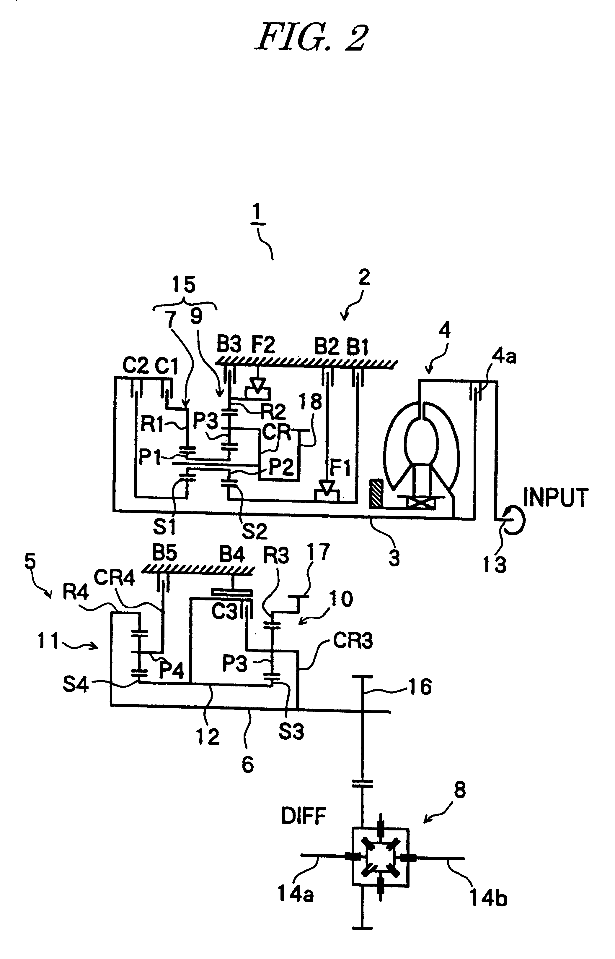
As shown in FIG. 2, a five-speed automatic transmission 1 is provided with a torque converter 4, a three-speed primary speed-change mechanism 2, a three-speed secondary speed-change mechanism 5 and a differential 8, which are interconnected to one another and accommodated in an integral-type casing. The torque converter 4 is provided with a lock-up clutch 4a. Power is inputted to an input shaft 3 of the primary speed-change mechanism 2 from an engine crank shaft 13 through oil flowing in the torque converter or through mechanical connection based on the lock-up clutch. The first shaft 3 (more specifically, input shaft), a second shaft 6 (counter shaft) and third shafts 14a and 14b (left and right vehicle axles) are rotatably supported by the integral-type casing. The first shaft 3 is aligned with the crank shaft, and the second shaft 6 and the third shafts 14a and 14b are parallel to ...


PUM


Abstract

In a multiple speed-change operation for switching between an up-shift operation and a down-shift operation, engine torque control is adapted to an actual change in speed-change state, whereby an abrupt change in rotational speed of the input shaft is prevented. One embodiment relates to a speed-change operation from the second speed to the third speed, wherein the engagement-side hydraulic pressure B4 rises and the release-side hydraulic pressure B5 drops, the rotational speed NT of the input shaft changes from a second speed state toward a third speed state and the engine torque TE is reduced by a predetermined amount TCU. If a command to perform a speed-change operation from the third speed to the second speed is issued during the aforementioned speed-change operation from the second speed to the third speed, control of the hydraulic pressures is switched to the speed-change operation from the third speed to the second speed. If it is detected because of the hydraulic pressure control that the direction of the change omega in rotational speed of the input shaft has changed toward the second speed, it is determined that the speed-change operation has actually started. Then, the torque reduction operation is suspended, and the torque is gradually restored.

Description

INCORPORATION BY REFERENCEThe disclosure of Japanese Patent Application No. HEI 10-311266 filed on Oct. 30, 1998 including the specification, drawings and abstract is incorporated herein by reference in its entirety.1. Field of the InventionThe present invention relates to a speed-change control apparatus for an automatic transmission that is installed in a motor vehicle and, more specifically, to a speed-change control apparatus for controlling both engine torque and hydraulic pressure for changing speed stages and, in particular, to a speed-change control apparatus which provides a multiple speed-change operation wherein, during a certain speed-change operation, a command to establish another speed stage is issued.2. Description of the Related ArtU.S. Pat. No. 4,688,450 discloses a speed-change control apparatus for changing engine torque during a speed-change operation. This speed-change control apparatus relates to speed-change control wherein during a certain (first) speed-chan...

Claims


Application Information

Patent Timeline
IPC IPC(8): F16H61/06F16H61/04F16H59/68B60W10/02B60W10/04B60W10/06B60W10/10B60W10/11F02D29/00F16H63/50
CPCB60W10/06B60W10/115B60W30/18F16H61/061B60K2741/065Y10T477/677F16H63/502F16H2059/6807F16H2059/425F16H2306/24B60W10/04B60W10/11B60W30/1819
Inventor KOJIMA, KOUICHITSUTSUI, HIROSHISAITOU, MASAONISHIDA, MASAAKIYAMAMOTO, YOSHIHISA
Owner AISIN AW CO LTD
Why Eureka
Try Eureka