Shaped piezoelectric composite transducer

Inactive Publication Date: 2001-07-03
THE UNITED STATES OF AMERICA AS REPRESENTED BY THE SECRETARY OF THE NAVY
View PDF8 Cites 25 Cited by
  • Summary
  • Abstract
  • Description
  • Claims
  • Application Information

AI Technical Summary

Problems solved by technology

Unfortunately, these assemblies are very expensive to design and fabricate.

Method used


Image

  • Shaped piezoelectric composite transducer
  • Shaped piezoelectric composite transducer
  • Shaped piezoelectric composite transducer

Examples


Embodiment Construction

)

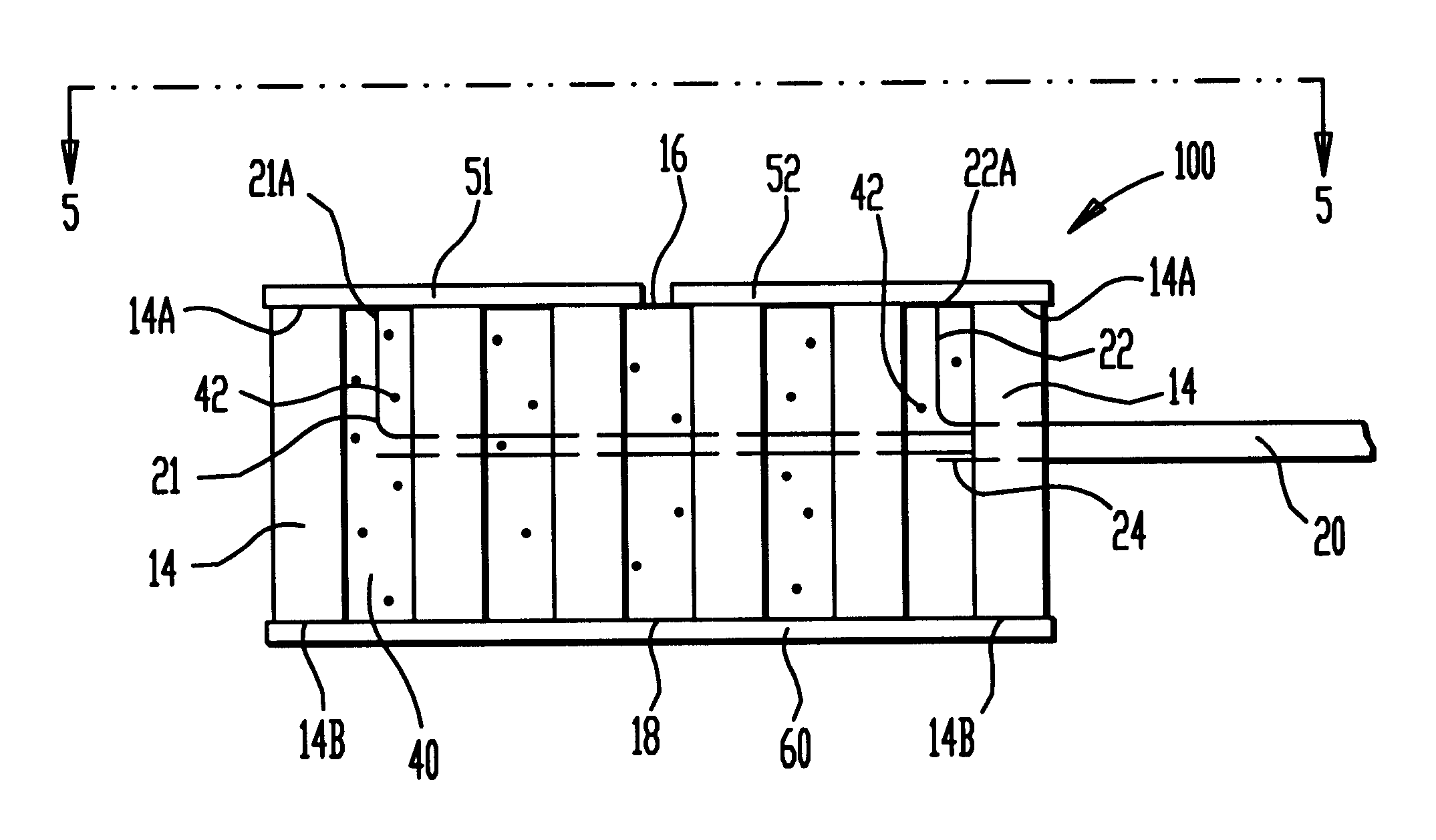
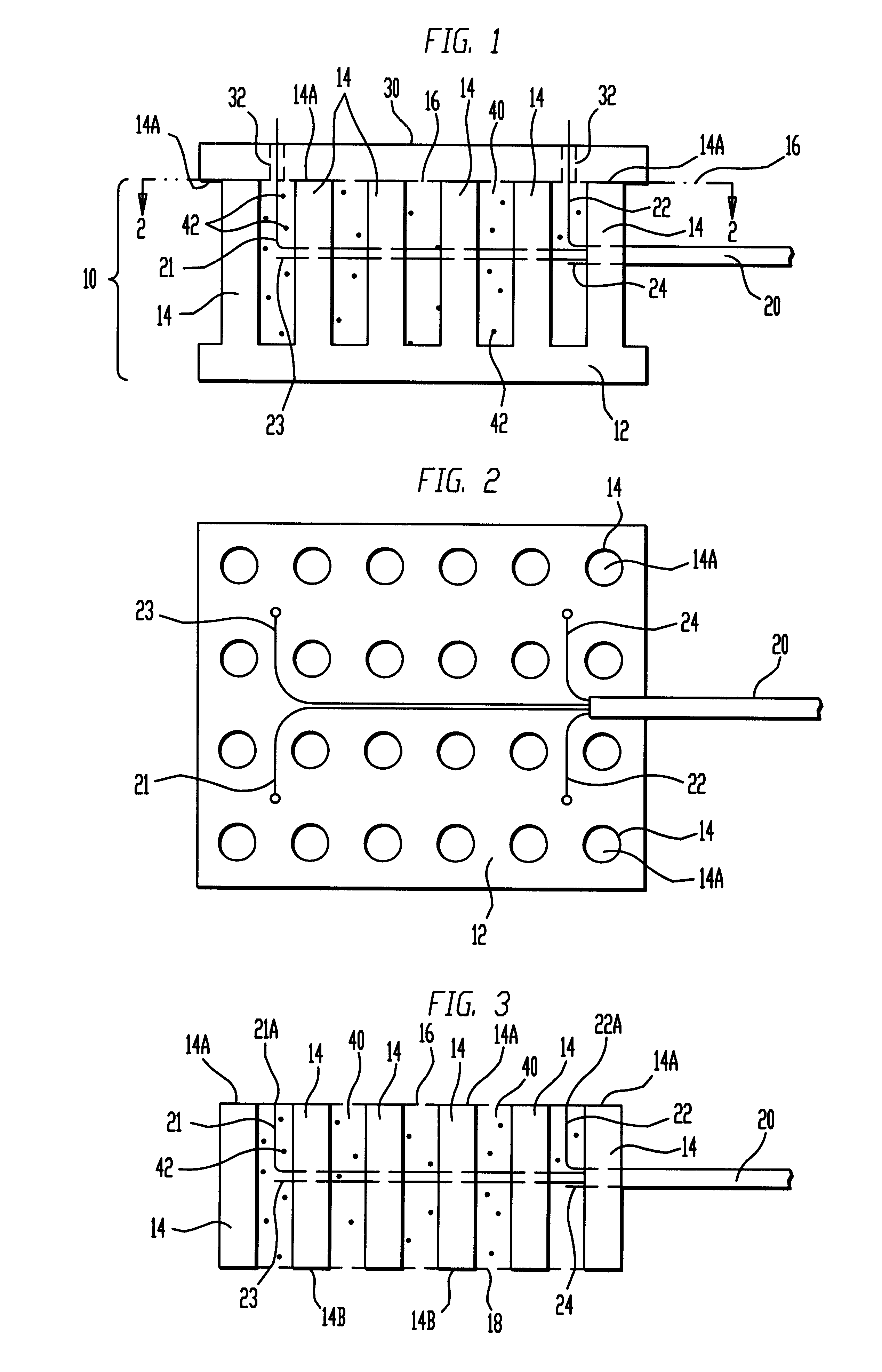
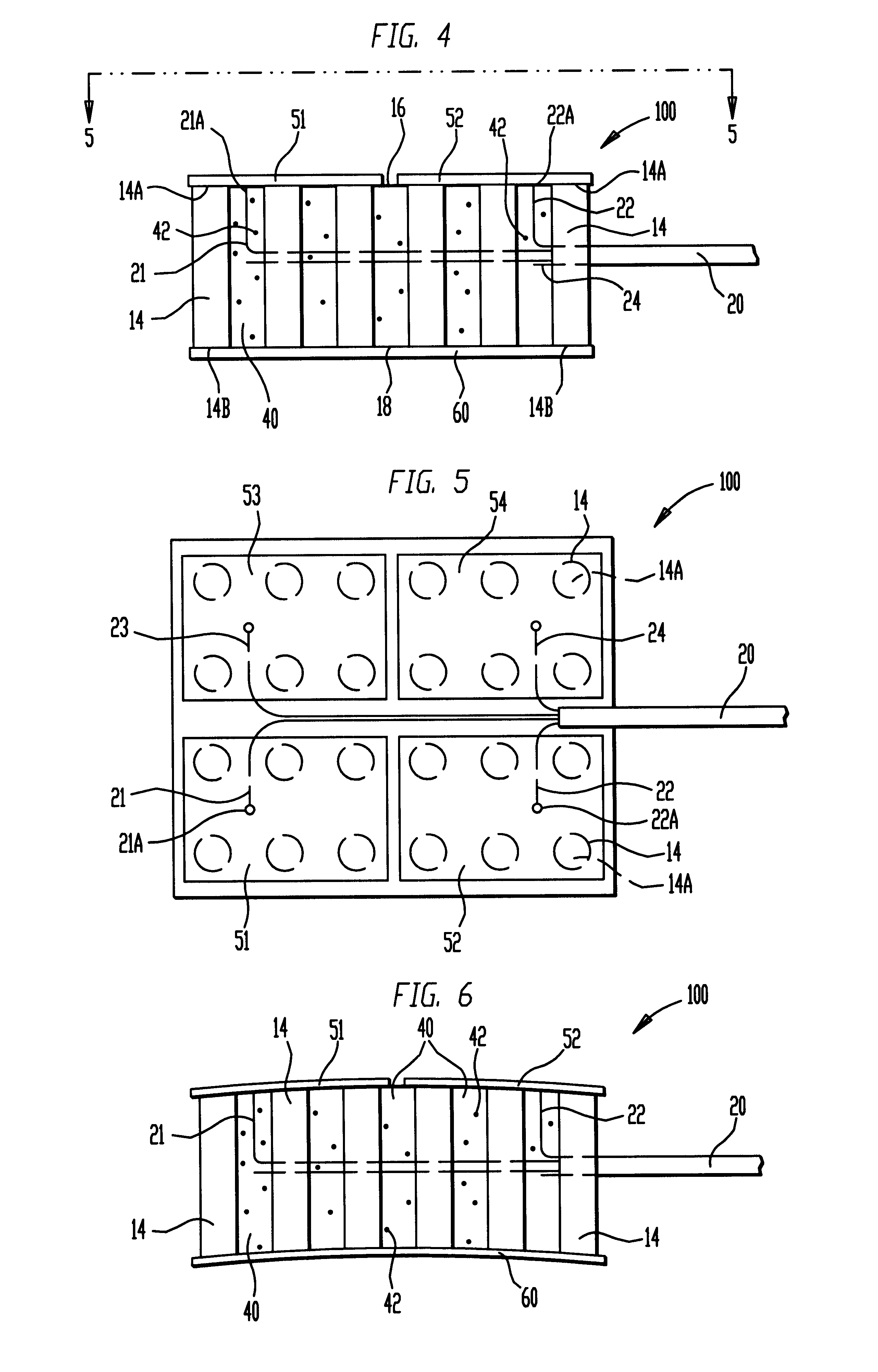
Referring now to the drawings, and more particularly to FIGS. 1 and 2, the first few steps of the composite transducer assembly fabrication method of the present invention will be described. A block of piezoelectric material (e.g., a ferroelectric material such as the piezoceramic materials lead zirconate titanate or lead titanate) is illustrated and referenced generally by numeral 10. Block 10 is defined by a base 12 and a plurality of spaced-apart columns or rods 14 extending from base 12. Typically, rods 14 are of uniform height and are parallel to one another such that their outboard ends 14A define a surface region indicated by dashed line 16 in FIG. 1. Rods 14 are typically arranged in a two-dimensional array as best seen in FIG. 2. Note that viscoelastic material 40 is omitted from FIG. 2 for clarity of illustration. Rods 14 can be fabricated with a circular cross-section as shown in FIG. 2. However, rods 14 can also be fabricated with a non-circular cross-section, e.g., tri...


PUM

PropertyMeasurementUnit
Lengthaaaaaaaaaa
Electric propertiesaaaaaaaaaa
Piezoelectricityaaaaaaaaaa

Abstract

A piezoelectric composite transducer and method for making same are disclosed. A block of piezoelectric material has a common base and a plurality of uniform-length rods extending from the common base in a parallel spaced-apart fashion to define an array. A first surface region is defined at outboard ends of the rods and a side region is defined about the periphery of the array. Electric conductors extend through the side region, are routed parallel to the first surface region, and are then led substantially parallel to the rods to the first surface region. Spaces between the rods are filled up to the first surface region with a viscoelastic material. The common base of the block is then removed such that a second surface region parallel and opposite to the first surface region is defined. Electrodes are deposited at the first surface region to be in contact with the rods and in electrical contact with the electric conductors. A ground electrode is deposited at the second surface region to be in contact with the rods. The resulting piezoelectric composite transducer can be heated and shaped to conform to complex curves.

Description

(1). Field of the InventionThe present invention relates generally to piezoelectric composite transducer assemblies, and more particularly to a piezoelectric composite transducer assembly that can be shaped into a complex curved configuration.(2). Description of the Prior ArtTransducer assemblies are frequently mounted on a supporting structure which currently must be a flat or simply curved surface. These situations can be handled by one-dimensionally curved transducers made from either injection molded 1-3 piezocomposites or flex circuits with composite conductive / non-conductive adhesive films. However, in many underwater acoustic applications, it is desirable to have a transducer assembly conform to a structure that presents a more complex curved surface. For example, most underwater vehicles are curved in one direction across the bow and curved in another direction from bow to stern. If the same transducer assembly must conform to both of these curves, the only option is to desi...

Claims


Application Information

Patent Timeline
IPC IPC(8): H01L41/18H04R17/00
CPCH04R17/00H01L41/37H01L41/183Y10T29/49005Y10T29/4908Y10T29/42Y10T29/4902Y10T29/49002H10N30/852H10N30/092
Inventor BENJAMIN, KIM C.
Owner THE UNITED STATES OF AMERICA AS REPRESENTED BY THE SECRETARY OF THE NAVY
Why Eureka
Try Eureka