Radial elastomeric spring arrangement to compensate for hull deflection at main bearing of a mooring turret

Inactive Publication Date: 2001-07-24
SOFEC
View PDF7 Cites 24 Cited by
  • Summary
  • Abstract
  • Description
  • Claims
  • Application Information

AI Technical Summary

Benefits of technology

A principal object of the invention is to provide a radial spring arrangement between main bearing of a mooring

Problems solved by technology

The radial springs do not have enough lateral stiffness to absorb the

Method used


Image

  • Radial elastomeric spring arrangement to compensate for hull deflection at main bearing of a mooring turret
  • Radial elastomeric spring arrangement to compensate for hull deflection at main bearing of a mooring turret

Examples


Embodiment Construction

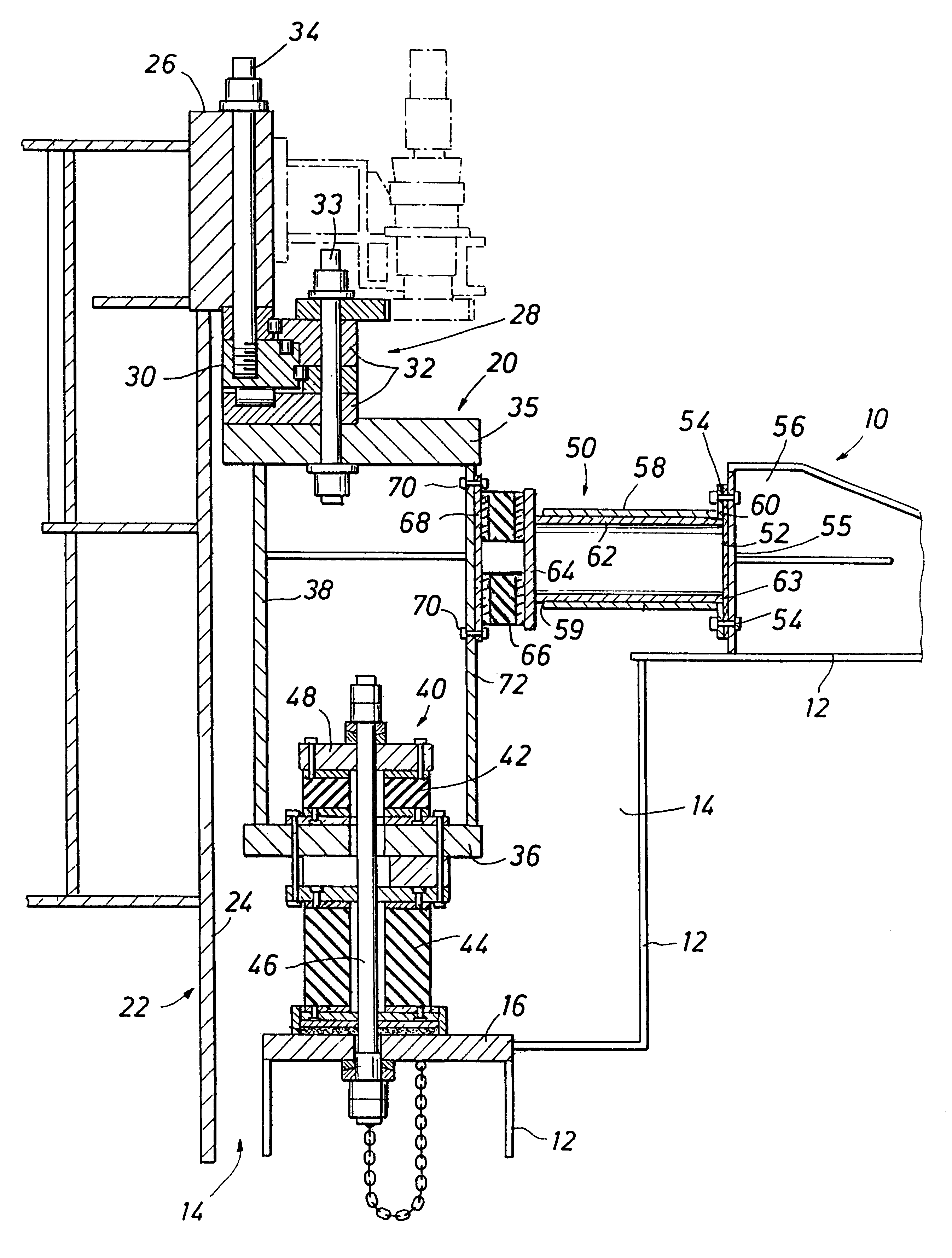
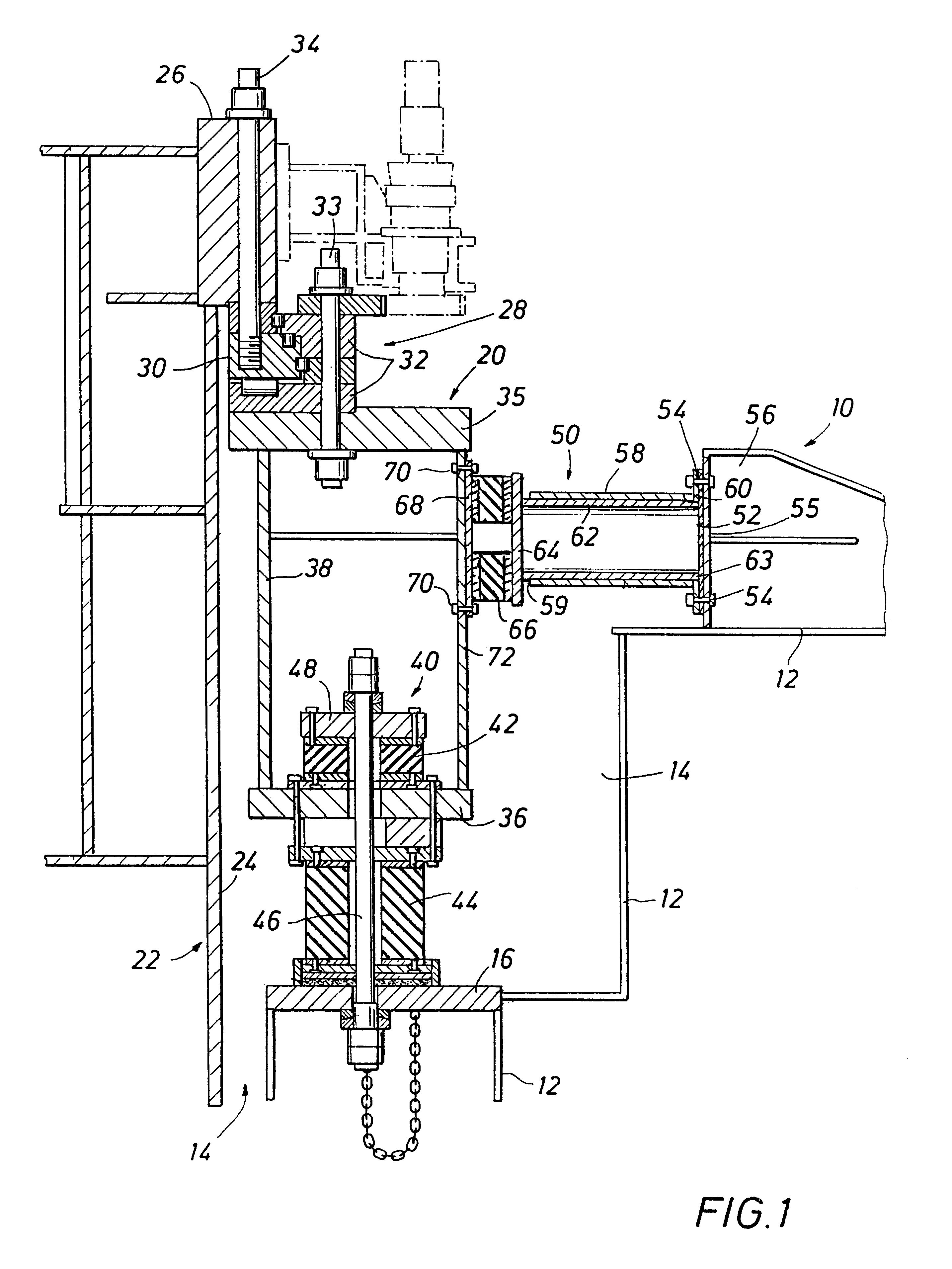
Referring to FIG. 1, a vessel shown at 10 has a hull 12 with a moon pool generally indicated at 14 extending through the hull or body 12 of vessel 10. A horizontal case support ring 16 on hull 12 adjacent moon pool 14 supports a spring assembly generally indicated at 20 for turret 22 mounted within moon pool 14. Turret 22 is anchored to the sea floor by a plurality of mooring lines (not shown), and vessel 10 weathervanes about turret 22 as well known.

A plurality of spring assemblies 20, such as twenty, for example, are equally spaced about the outer periphery 24 of turret 22. FIG. 1 shows a single spring assembly for illustration. Turret 22 has an upper turret shear ring 26 extending outwardly from the outer periphery 24 of turret 22. Shear ring 26 supports turret 22 on a main upper bearing generally indicated at 28 including an inner ring or race 30 mounted on bearings within outer ring or race 32. Suitable studs 34 secure turret shear ring 26 to inner bearing ring or race 30 and o...


PUM


Abstract

Elastomeric pads are arranged radially around the main bearing which rotatably supports a mooring turret with respect to a vessel. The elastomeric pads act as radial springs to react the radial turret loads in the vessel and to compensate for ovaling of the vessel in response to sea environmental forces on the vessel. A radial spring assembly is provided which applies compressive load to the elastomeric pads when the vessel and turret move radially toward each other, but prevent tension from being applied to the pads when the vessel and turret move radially away from each other.

Description

1. Field of the InventionThis invention relates generally to turret moored offshore vessels and in particular to a radial elastomeric spring arrangement for the main bearing of a mooring turret to compensate for hull deflections or distortions of the moored vessel.2. Description of the Prior ArtHeretofore, elastomeric springs have been provided for supporting an upper bearing of a mooring turret for a moored vessel. For example, U.S. Pat. No. 5,515,804 dated May 14, 1996 shows a bearing support for a mooring turret in which a plurality of equally spaced resilient support structures support the upper bearing. Each support structure includes a post secured to the turret and extending downwardly from the turret at a 45 degree angle with a plurality of elastomeric shear pads between upper and lower post portions of each post The heavy weight of the mooring chains causes bending of an upper hull beam and the shear pads in the posts may move closer together or further apart as a result of...

Claims


Application Information

Patent Timeline
IPC IPC(8): B63B21/50B63B21/00
CPCB63B21/507
Inventor FONTENOT, WILLIAM L.HOBDY, MILES A.BOATMAN, L. TERRY
Owner SOFEC
Why Eureka
Try Eureka