Eye shield assembly

a technology of eye shields and assemblies, applied in the field of eye shields, can solve the problems of obstructing affecting the vision of the person wearing the hat, and the use of the eye shield assembly has not been wholly satisfactory, so as to achieve the effect of enabling unobstructed vision

Inactive Publication Date: 2001-08-21
JAMIN SUN SHAYDES
View PDF10 Cites 31 Cited by
  • Summary
  • Abstract
  • Description
  • Claims
  • Application Information

AI Technical Summary

Benefits of technology

The frame is pivotally mounted to the brim so that the frame is movable between a storage position and an operational position. In its storage position, the lens nests closely adjacent to and conforms to the shape of the brim, thus enabling unobstructed vision for the person wearing the hat. Conversely, in its operational position, the frame with its attached lens depends generally perpendicularly downwardly from the frame. In doing so, the lenses are positioned in series with the line of vision for the person wearing the hat.

Problems solved by technology

These previously known eye shield assemblies, however, have not proven wholly satisfactory in use.
One disadvantage of these previously known devices is that the eye shield assembly, even when in a storage position, obstructs the vision of the person wearing the hat since the eye shield assembly does not conform to the shape of the brim when in its storage position.
In use, however, the eye shield assembly may become skewed relative to the person wearing the hat.
A still further disadvantage of these previously known devices is that the eye shield assembly was directly and permanently mounted to the hat brim.
Consequently, the eye shield assembly could not be moved from one hat and to another.

Method used


Image

  • Eye shield assembly
  • Eye shield assembly
  • Eye shield assembly

Examples


Embodiment Construction

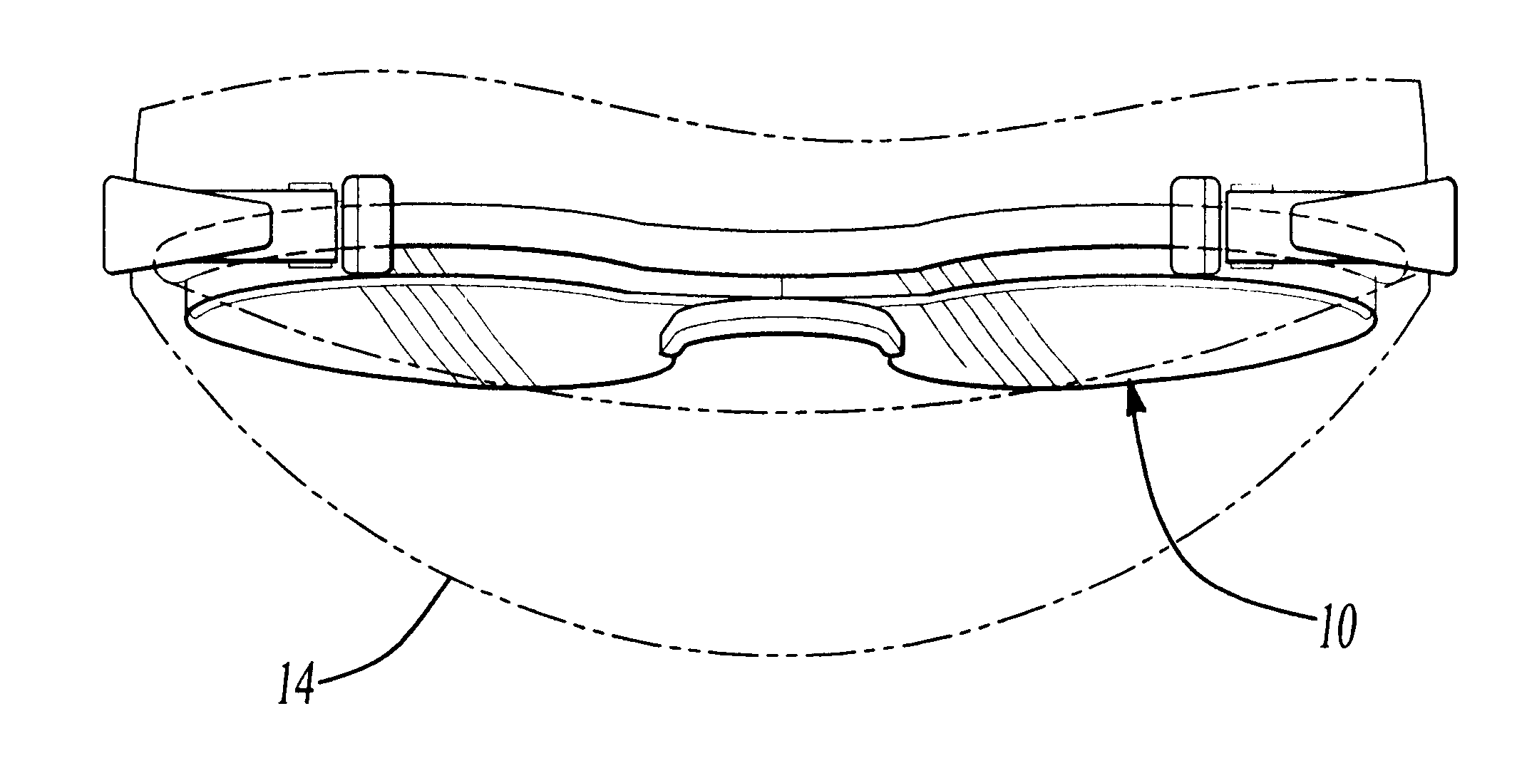
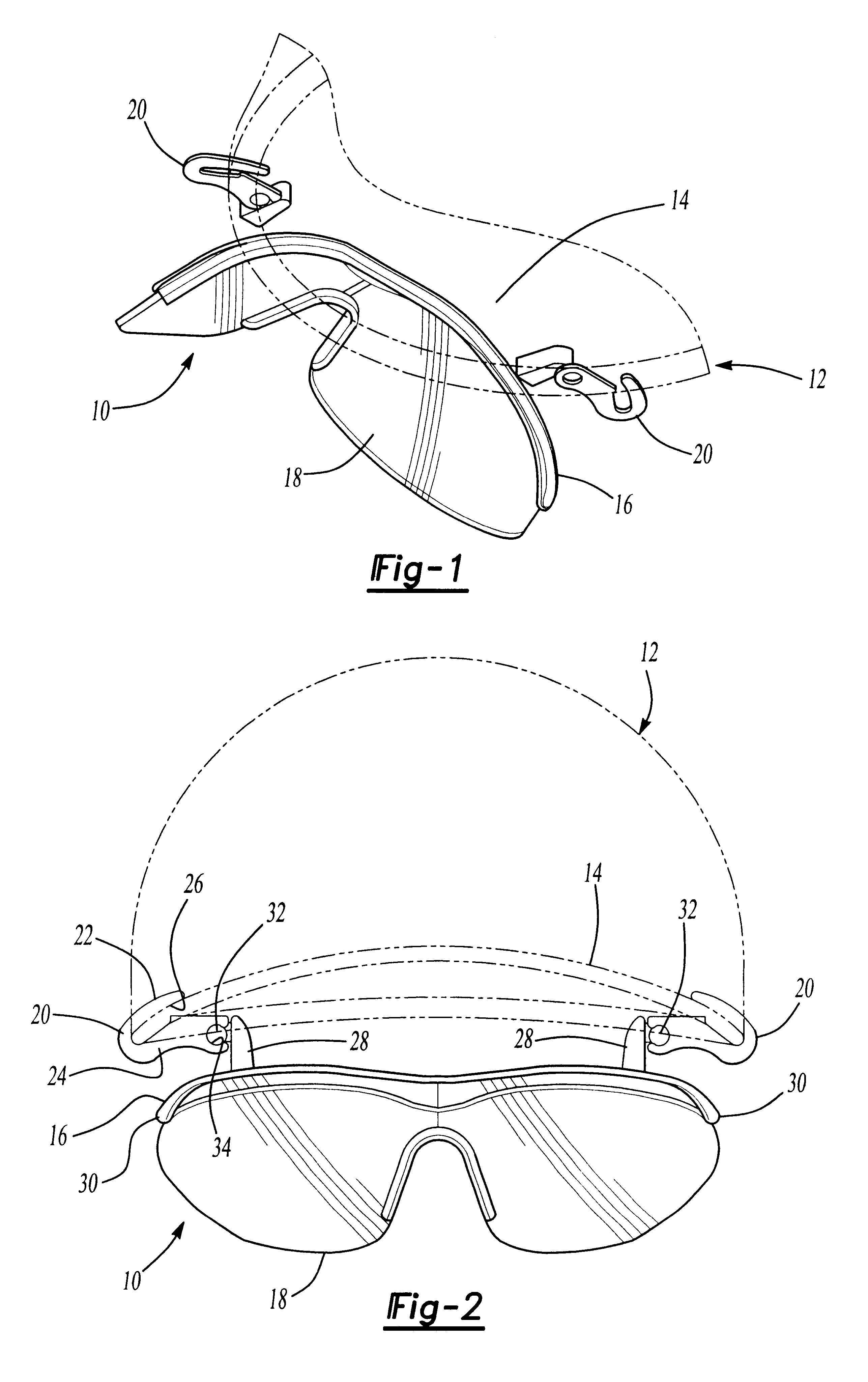
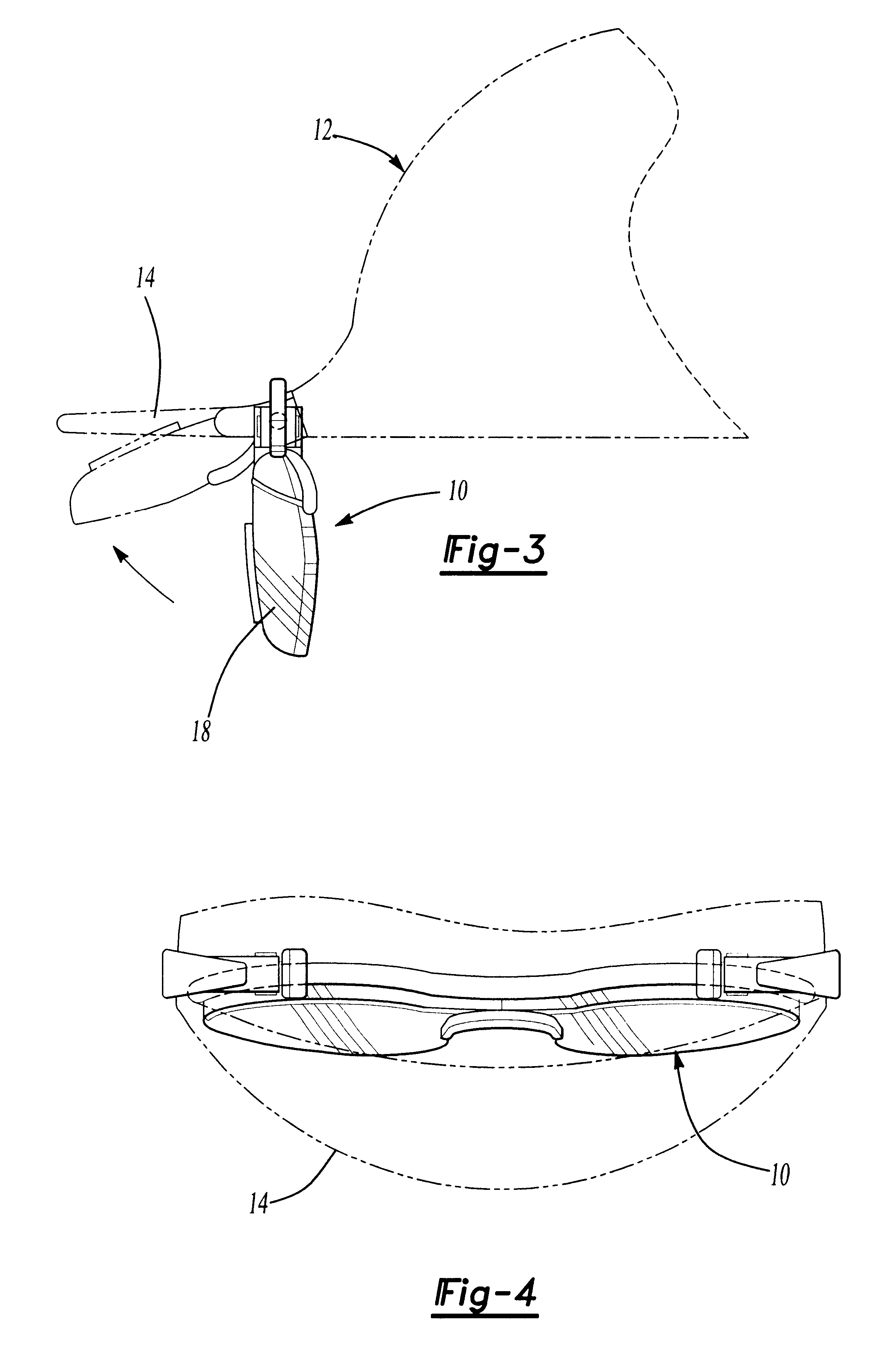
With reference first to FIGS. 1 and 2, a preferred embodiment of an eye shield assembly 10 is there shown for use with a hat 12 having a brim 14. As best shown in FIG. 2, the brim 14 has a generally concave shape and, when the hat 12 is worn, the brim 14 projects forwardly from the wearer's face.

The eye shield assembly 10 generally comprises a frame 16 which is preferably made of plastic. The frame 16 is secured to and supports a preferably concave transparent lens 18 in any conventional fashion. Furthermore, the lens 18 may optionally be tinted so that, when placed in the line of vision of the person wearing the hat, the lens 18 operates as a pair of sunglasses.

Still referring to FIGS. 1 and 2, in order to secure the frame 16 to the hat brim 14, the eye shield assembly 10 includes a pair of C clips 20. Each C clip 20 includes a pair of arms 22 and 24 such that a slot 26 is formed between the arms 22 and 24.

The slot 26 has a width less than the thickness of the brim 14. Furthermore,...


PUM


Abstract

An eye shield assembly is provided for use in conjunction with a hat having a brim. The eye shield assembly includes a frame and a lens mounted to the frame. The opposite sides of the frame are pivotally secured to the hat brim so that the frame is movable between a storage position and an operational position. In its storage position, the lens nests closely adjacent to the brim while in the operational position, the lens depends generally perpendicularly downwardly from the brim.

Description

I. Field of the InventionThe present invention relates generally to eye shields and, more particularly, to an eye shield which is detachably secured to the brim of a hat.II. Description of the Prior ArtThere have been a number of previously known eye shield assemblies, oftentimes tinted, which are attached to the brim of a hat. Such assemblies have been used not only in athletics, but also for casual wear. Some of these previously known eye shield assemblies, furthermore, have been pivotally mounted to the hat brim between the storage and an operational position.These previously known eye shield assemblies, however, have not proven wholly satisfactory in use. One disadvantage of these previously known devices is that the eye shield assembly, even when in a storage position, obstructs the vision of the person wearing the hat since the eye shield assembly does not conform to the shape of the brim when in its storage position.Additionally, some of these previously known devices have ut...

Claims


Application Information

Patent Timeline
Patent Type & Authority Patents(United States)
IPC IPC(8): G02C3/00G02C3/02G02C9/02G02C9/00A42B1/18
CPCA42B1/247G02C9/02G02C3/02
Inventor BONDY, DENNIS MICHAEL
Owner JAMIN SUN SHAYDES
Why Eureka
Try Eureka