Lens delivery system

a delivery system and lens technology, applied in the field of lenses, can solve the problems of poor design, vision deterioration, and potential damage to the lens, and achieve the effect of less than optimal design when used with viscoelastic materials such as soft acryli

Active Publication Date: 2007-01-02
ALCON INC
View PDF25 Cites 233 Cited by
  • Summary
  • Abstract
  • Description
  • Claims
  • Application Information

AI Technical Summary

Benefits of technology

[0006]The present invention improves upon prior art by providing a lens delivery system having a plunger, an injector body and a nozzle portion connected to the injector body, the nozzle portion having a hinged lid and a hollow body with a lens holding platform formed beneath the hinged lid. The inside of the hinged lid contains ribs that help to hold a lens stationary on the platform when the lid is closed. The cartridge has an elongated nozzle tube or tip with a bore, the bore communicating with the lens holding platform. The bottom of the bore is rounded, which causes the edges of the lens between the lens haptics to fold upwardly as the lens is pushed down the bore from the platform by the plunger. The centr

Problems solved by technology

When trauma, age or disease cause the lens to become less transparent, vision deteriorates because of the diminished light which can be transmitted to the retina.
This requires additional handling of the lens, with

Method used


Image

  • Lens delivery system
  • Lens delivery system
  • Lens delivery system

Examples


Embodiment Construction

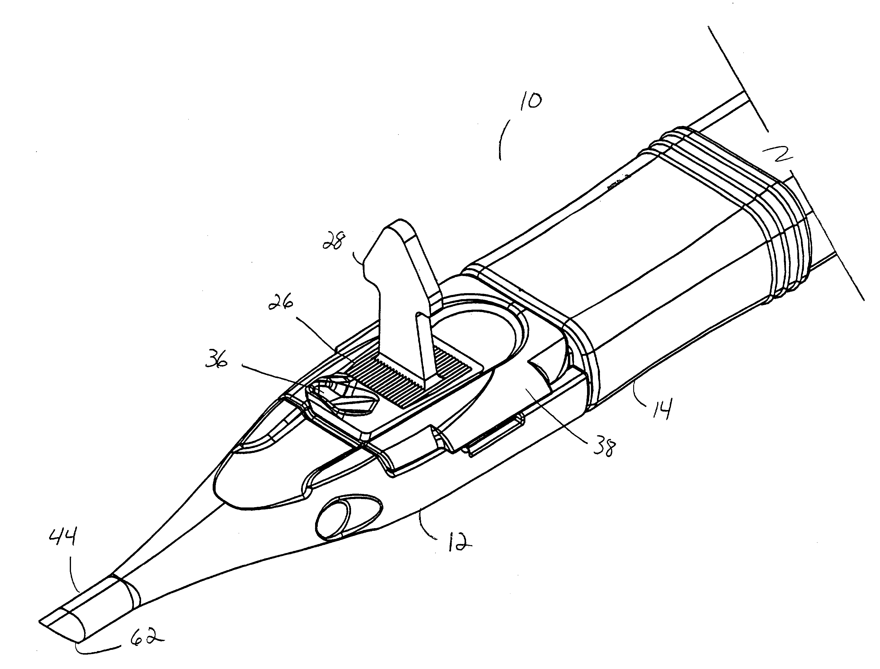
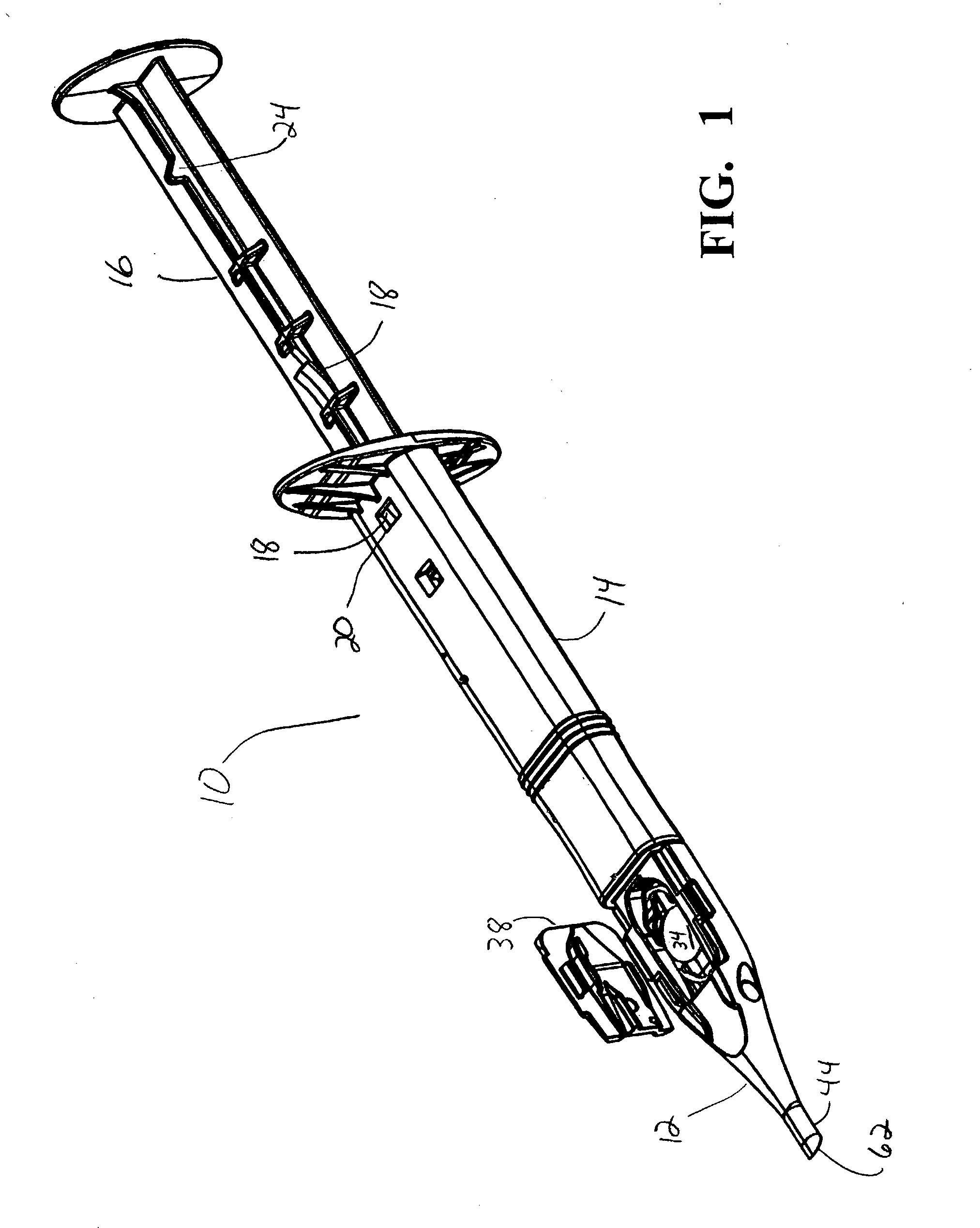
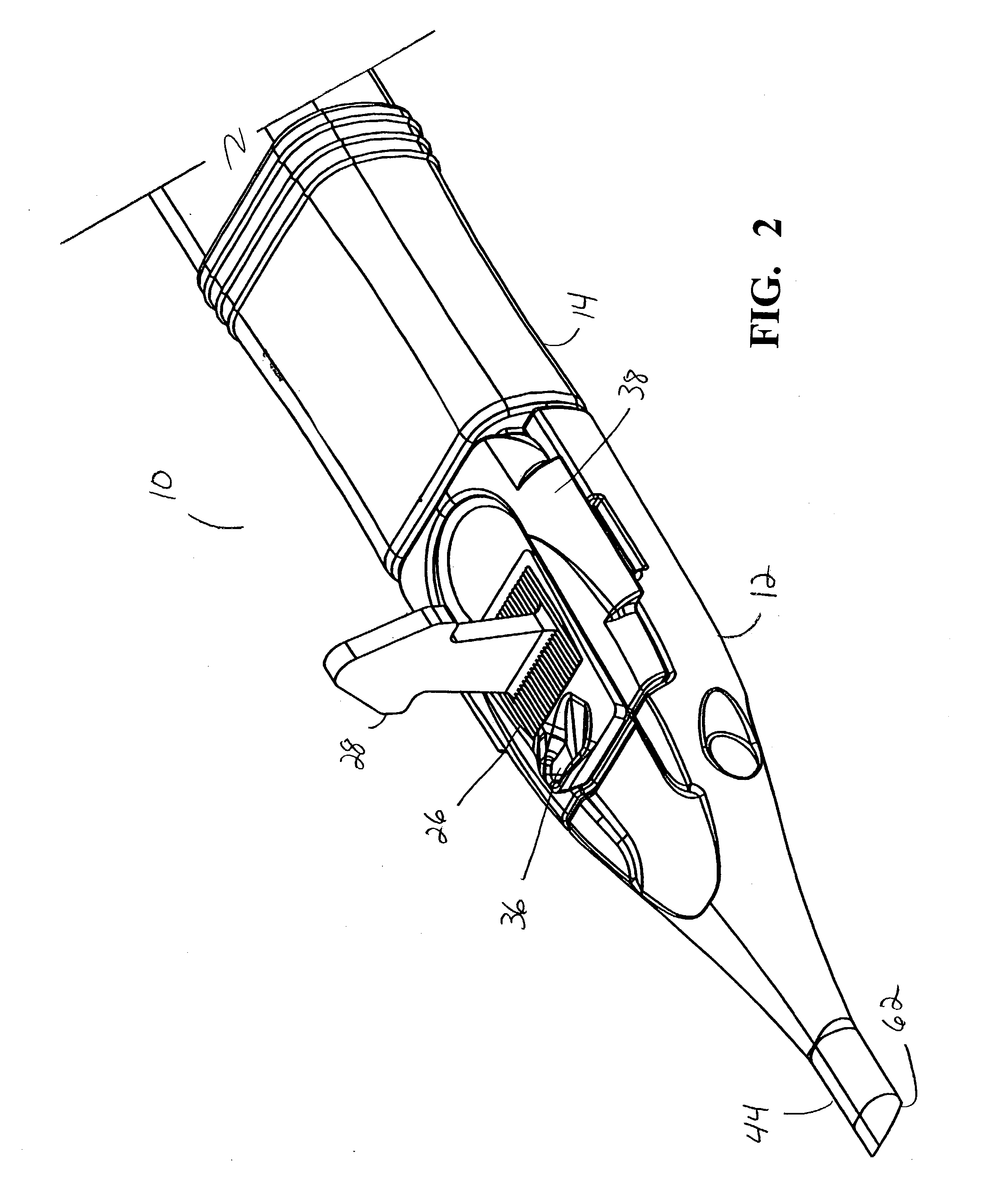
[0020]As best seen in FIG. 1, lens delivery system 10 of the present invention generally includes nozzle portion 12, injector body 14 and plunger 16. Plunger 16 contains a plurality of spring tabs 18 that cooperate with slot 20 on injector body 14 to prevent unwanted or unintended rearward (proximal) movement of plunger 16 during shipment or use. Plunger 16 also contains rigid tab 24 that cooperates with injector body 14 to prevent plunger 16 from being pushed too far forward (distally) during use. Nozzle portion 12, injector body 14 and plunger 16 are preferably molded from a suitable thermoplastic, such as polypropylene. As best seen in FIGS. 10 and 11, distal tip 17 of plunger 16 contains biasing tab 19 that holds tip 17 tightly within injector body 14 during shipment, but allows tip 17 to pass through relatively small distal nozzle tube 44 during delivery of IOL 34. Chin 21 on tip 17 helps keep tip 17 from being pushed up and over IOL 34 during delivery of IOL 34.

[0021]As best s...


PUM


Abstract

A lens delivery system having a plunger, an injector body and a nozzle portion connected to the injector body, the nozzle portion having a hinged lid and a hollow body with a lens holding platform formed beneath the hinged lid. The cartridge has an elongated nozzle tube or tip with a bore, the bore communicating with the lens holding platform. The bottom of the bore is rounded, which causes the edges of the lens between the lens haptics to fold upwardly as the lens is pushed down the bore from the platform by the plunger. A removable pin fits into the lid and prevents the lens from moving down the bore of the tip during shipment and storage.

Description

[0001]This invention relates to intraocular lenses (IOLs) and more particularly to devices use to inject IOLs into an eye.BACKGROUND OF THE INVENTION[0002]The human eye in its simplest terms functions to provide vision by transmitting and refracting light through a clear outer portion called the cornea, and further focusing the image by way of the lens onto the retina at the back of the eye. The quality of the focused image depends on many factors including the size, shape and length of the eye, and the shape and transparency of the cornea and lens.[0003]When trauma, age or disease cause the lens to become less transparent, vision deteriorates because of the diminished light which can be transmitted to the retina. This deficiency in the lens of the eye is medically known as a cataract. The treatment for this condition is surgical removal of the lens and implantation of an artificial lens or IOL.[0004]While early IOLs were made from hard plastic, such as polymethylmethacrylate (PMMA)...

Claims


Application Information

Patent Timeline
IPC IPC(8): A61F9/00A61F2/16
CPCA61F2/1678A61F2/1691F16L23/032F16L23/024F16L23/22F16L43/008
Inventor BROWN, KYLEDOWNER, DAVID A.HEYMAN, THOMAS M.
Owner ALCON INC
Why Eureka
Try Eureka