

Imaging catheter with integrated reference reflector
a reference reflector and imaging catheter technology, applied in the field of optical imaging, can solve problems such as substantially undistorted imaging light transmission
- Summary
- Abstract
- Description
- Claims
- Application Information
AI Technical Summary
Benefits of technology
Problems solved by technology
Method used
Image

Examples
Embodiment Construction
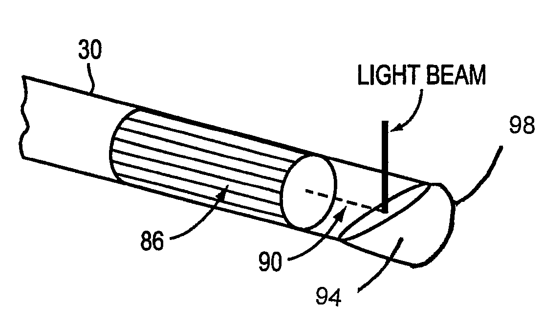
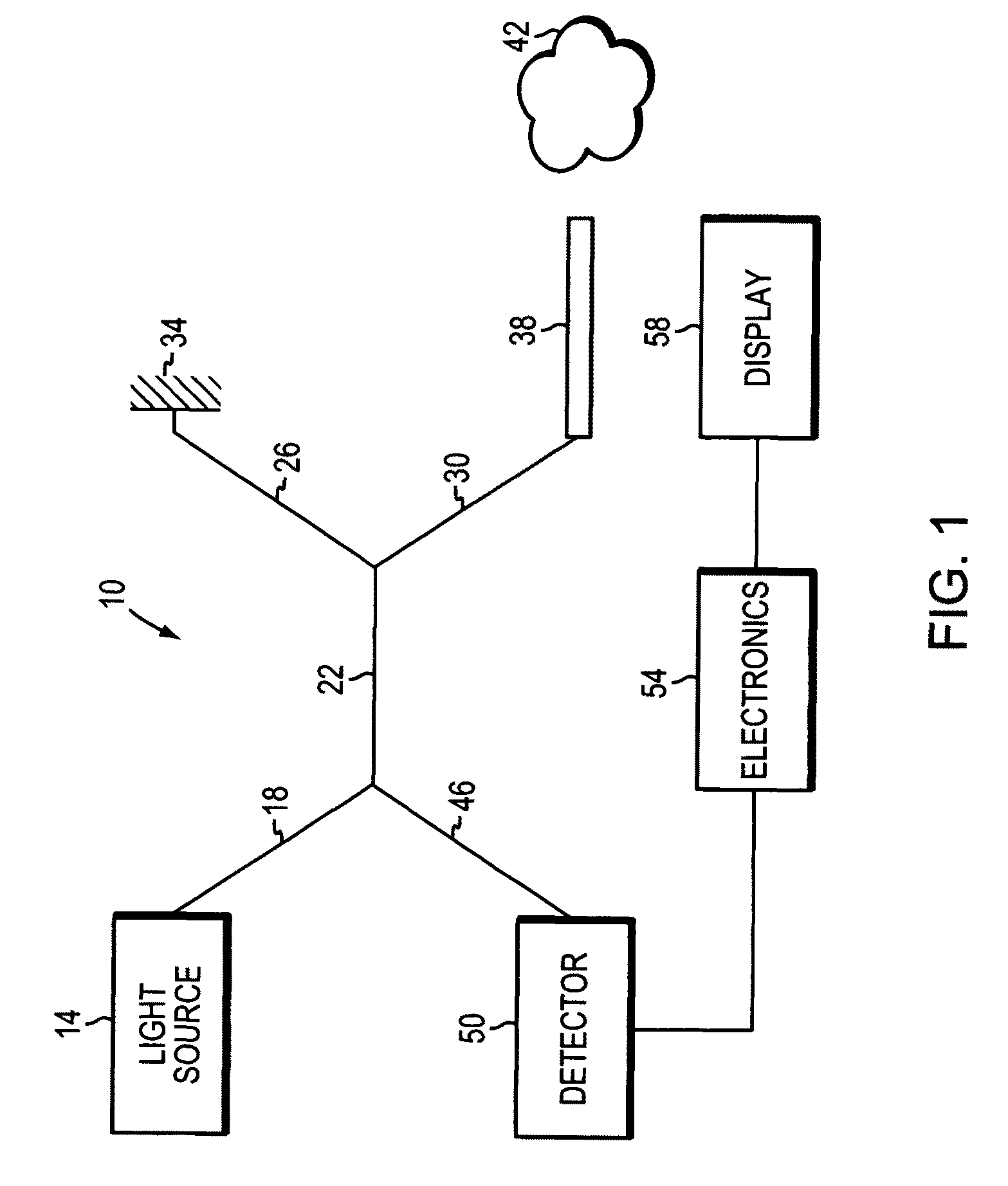
[0037]In brief overview and referring to FIG. 1, a generalized OCT interferometer 10 is shown which is suitable for use with the catheter imaging system of the invention. A light source 14, such as a diode laser, produces short-coherence length light that passes by way of an optical fiber 18 into an optical fiber coupler 22. Light entering the coupler 22 is the split along two optical fiber paths 26 and 30. One path 26 terminates at a movable reflector 34, while the other enters a probe 38 and is emitted toward an object of interest 42.
[0038]Light reflected by the movable reflector 34 passes back along optical fiber 26 to the coupler 22. Similarly light reflected by the object of interest 42 passes back along optical fiber 30 to the coupler 22 and combines with the light reflected by the movable reflector 34 to form an interference pattern. This combined light passes through optical fiber 46 and is detected by a detector 50. The output signal from the detector 50 is processed by ele...
PUM
 Abstract
Description
Claims
Application Information