

Imaging optical lens assembly
a technology of optical lens and assembly, applied in the field of imaging optical lens assembly, can solve the problem that the photographing lens requires higher power consumption, and achieve the effect of reducing the number of lens groups, less power consumption, and improving the image quality of the imaging optical lens assembly
- Summary
- Abstract
- Description
- Claims
- Application Information
AI Technical Summary
Benefits of technology
Problems solved by technology
Method used
Image

Examples
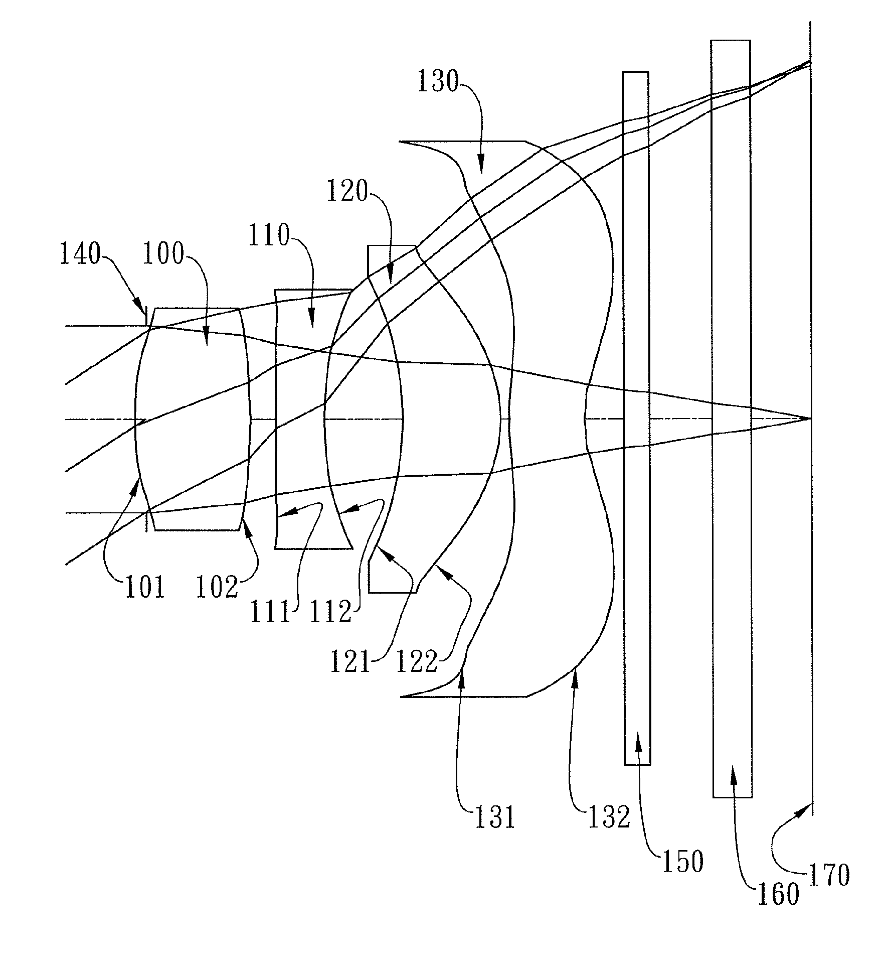
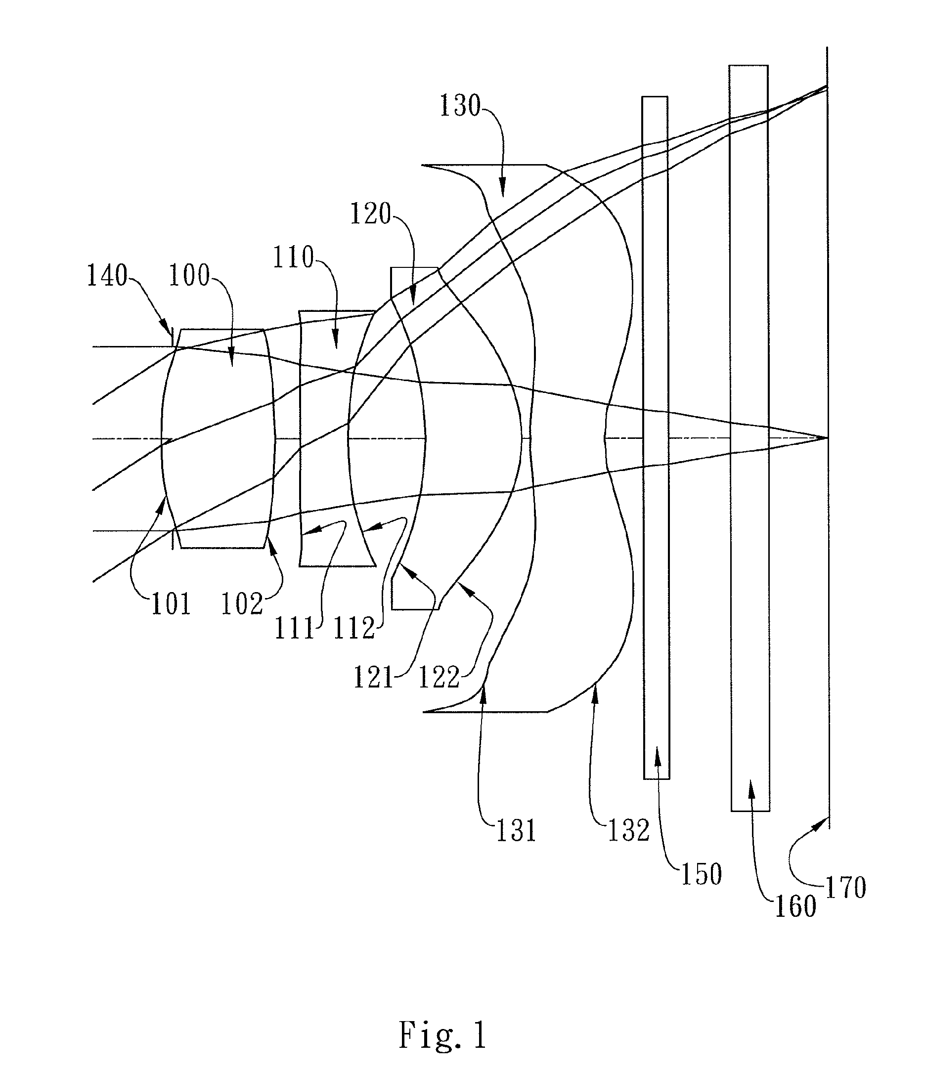
first embodiment
[0069]In the present imaging optical lens assembly, the maximum focal length of the imaging optical lens assembly is fmax, the minimum focal length of the imaging optical lens assembly is fmin, and they satisfy the relation: fmax / fmin=1.02.
[0070]In the first embodiment of the present imaging optical lens assembly, the back focal length of the imaging optical lens assembly is BFL1 when the first lens element 100 is positioned closest to the imaged object, the back focal length of the imaging optical lens assembly is BFL2 when the first lens element 100 is positioned closest to the image plane 170, and they satisfy the relation: |BFL1−BFL2|=0.0.
[0071]In the first embodiment of the present imaging optical lens assembly, the on-axis spacing between the image-side surface 102 of the first lens element 100 and the image plane 170 is D1 when the first lens element 100 is positioned closest to the imaged object, the on-axis spacing between the image-side surface 102 of the first lens elemen...
second embodiment
[0090]In the present imaging optical lens assembly, the maximum focal length of the imaging optical lens assembly is fmax, the minimum focal length of the imaging optical lens assembly is fmin, and they satisfy the relation: fmax / fmin=1.03.
[0091]In the second embodiment of the present imaging optical lens assembly, the back focal length of the imaging optical lens assembly is BFL1 when the first lens element 300 is positioned closest to the imaged object, the back focal length of the imaging optical lens assembly is BFL2 when the first lens element 300 is positioned closest to the image plane 370, and they satisfy the relation: |BFL1−BFL2|=0.0.
[0092]In the second embodiment of the present imaging optical lens assembly, the on-axis spacing between the image-side surface 302 of the first lens element 300 and the image plane 370 is D1 when the first lens element 300 is positioned closest to the imaged object, the on-axis spacing between the image-side surface 302 of the first lens elem...
third embodiment
[0111]In the present imaging optical lens assembly, the maximum focal length of the imaging optical lens assembly is fmax, the minimum focal length of the imaging optical lens assembly is fmin and they satisfy the relation: fmax / fmin=1.03.
[0112]In the third embodiment of the present imaging optical lens assembly, the back focal length of the imaging optical lens assembly is BFL1 when the first lens element 500 is positioned closest to the imaged object, the back focal length of the imaging optical lens assembly is BFL2 when the first lens element 500 is positioned closest to the image plane 570, and they satisfy the relation: |BFL1−BFL2|=0.0.
[0113]In the third embodiment of the present imaging optical lens assembly, the on-axis spacing between the image-side surface 502 of the first lens element 500 and the image plane 570 is D1 when the first lens element 500 is positioned closest to the imaged object, the on-axis spacing between the image-side surface 502 of the first lens element...
PUM
 Abstract
Description
Claims
Application Information