Lens holder driving device including damper compound suppressing undesired resonance

a driving device and lens holder technology, applied in the direction of instruments, printers, cameras, etc., can solve the problems of unfavorable stability of operation, and unfavorable automatic focusing lens driving device (the moving portion of the lens holder) to achieve the effect of carrying out operation with stability

Active Publication Date: 2013-02-28
MITSUMI ELECTRIC CO LTD
View PDF10 Cites 225 Cited by
  • Summary
  • Abstract
  • Description
  • Claims
  • Application Information

AI Technical Summary

Benefits of technology

[0015]It is therefore an exemplary object of the present invention to provide a le

Problems solved by technology

Therefore, there is a problem in which the auto-focusing lens driving device (the lens holder moving portion) resonates undesirably.
As a result, in the manner similar to the image stabilizer disclosed in Pate

Method used


Image

  • Lens holder driving device including damper compound suppressing undesired resonance
  • Lens holder driving device including damper compound suppressing undesired resonance
  • Lens holder driving device including damper compound suppressing undesired resonance

Examples


first exemplary embodiment

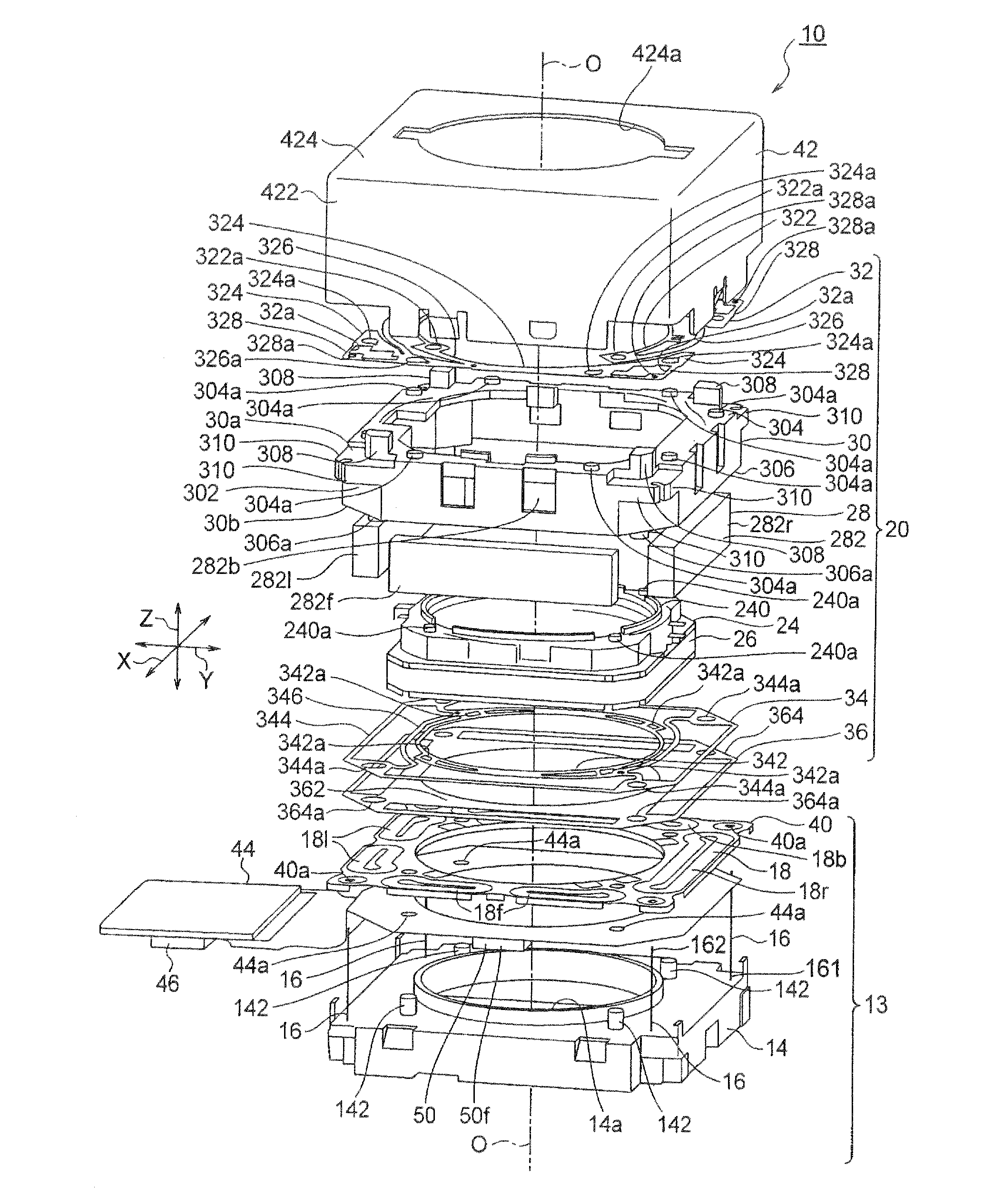
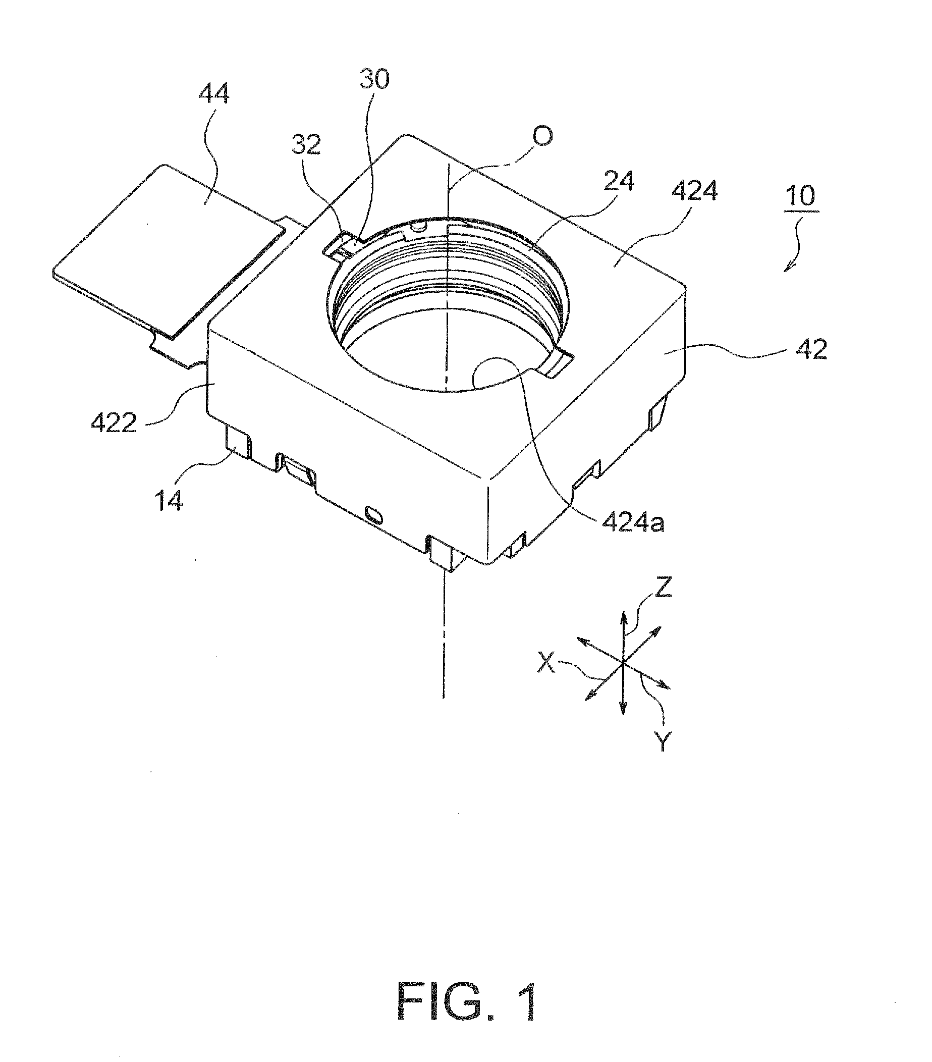
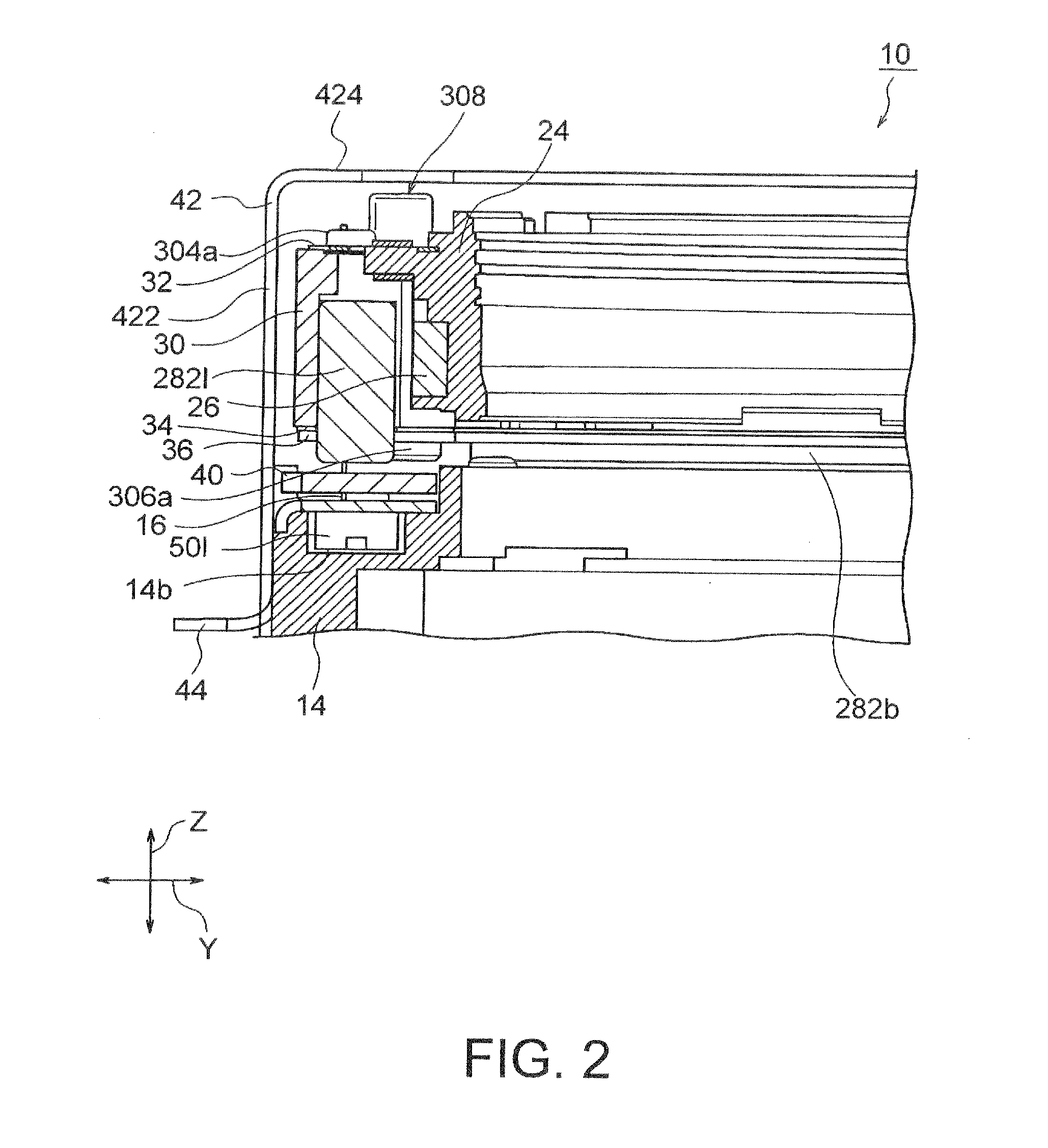
[0070]Referring to FIGS. 1 through 3, the description will proceed to a lens holder driving device 10 according to a first exemplary embodiment of this invention. FIG. 1 is an external perspective view of the lens holder driving device 10. FIG. 2 is a partial vertical cross sectional view of the lens holder driving device 10. FIG. 3 is an exploded perspective view of the lens holder driving device 10.

[0071]Herein, in the manner shown in FIGS. 1 through 3, an orthogonal coordinate system (X, Y, Z) is used. In a state illustrated in FIGS. 1 through 3, in the orthogonal coordinate system (X, Y, X), an X-axis direction is a fore-and-aft direction (a depth direction), a Y-axis direction is a left-and-right direction (a width direction), and a Z-axis direction is an up-and-down direction (a height direction). In addition, in the example being illustrated in FIGS. 1 through 3, the up-and-down direction Z is a direction of an optical axis O of a lens. In the first exemplary embodiment, the ...

second exemplary embodiment

[0247]Referring to FIGS. 35 through 37, the description will proceed to a lens holder driving device 10A according to a second exemplary embodiment of the present invention. FIG. 35 is an external perspective view of the lens holder driving device 10A. FIG. 36 is a partial vertical cross sectional view of the lens holder driving device 10A. FIG. 37 is an exploded perspective view of the lens holder driving device 10A.

[0248]Herein, in the manner shown in FIGS. 35 to 37, an orthogonal coordinate system (X, Y, Z) is used. In a state illustrated in FIGS. 35 to 37, in the orthogonal coordinate system (X, Y, X), an X-axis direction is a fore-and-aft direction (a depth direction), a Y-axis direction is a left-and-right direction (a width direction), and a Z-axis direction is an up-and-down direction (a height direction). In addition, in the example being illustrated in FIGS. 35 to 37, the up-and-down direction Z is a direction of an optical axis O of a lens. In the second exemplary embodim...

modified examples

[0273]Now, the description will proceed to modified examples of the lens holder driving device 10A according to the second exemplary embodiment.

[0274]Although the four damper compounds 65 are provided at the four locations as shown in FIG. 43 in the above-mentioned lens holder driving device 10A according to the second exemplary embodiment, the number of the damper compounds 65 and configuration thereof are not important in this invention, it is therefore important that the damper compound 65 is disposed between a movable portion (the auto-focusing lens holder driving portion) 20A and the fixed member 13.

[0275]By way of illustration, one damper compound 65 may be provided at only one location as the lens holder driving device 10A according to a first modified example in the manner as illustrated in FIG. 46. In addition, three damper compounds 65 may be provided at three locations as the lens holder driving device 10A according to a second modified example in the manner as illustrate...


PUM


Abstract

A lens holder driving device includes a lens holder moving portion, a fixed member, suspension wires, and a damper compound. In the lens holder moving portion, a lens holder moves in an optical axis and in first and second directions which are orthogonal to the optical axis and which are perpendicular to each other. The fixed member is disposed apart from the lens holder moving portion in the direction of the optical axis. The suspension wires have first end portions fixed to the fixed member at outer regions thereof, extending along the optical axis, having second end portions fixed to an elastic member mounted to the lens holder moving portion, and swingably supporting the lens holder moving portion in the first direction and the second direction. The damper compound is disposed so as to enclose at least one suspension wire and suppresses undesired resonance in the lens holder moving portion.

Description

[0001]This application is based upon and claims the benefit of priority from Japanese Patent Application No. JP-2011-182462, filed on Aug. 24, 2011, and Japanese Patent Application No. JP-2012-81688, filed on Mar. 30, 2012, the disclosures of which are incorporated herein in their entirety by reference.BACKGROUND OF THE INVENTION[0002]This invention relates to a lens holder driving device and, in particular, to a lens holder driving device capable of picking up a still image without blurry images by stabilizing the blurry images (movement) occurring upon shooting the still image using a miniature camera for a mobile terminal.[0003]Hitherto, various lens holder driving devices has been proposed which are capable of taking photographs with a high degree by stabilizing blurry images on an image-forming surface although there are blurry images (movement) upon shooting the still image.[0004]By way of illustration, two of the present co-inventors proposed an image stabilizer which is capa...

Claims


Application Information

Patent Timeline
IPC IPC(8): G02B27/64
CPCG02B27/64H04N5/2253H04N5/2254G03B2205/0069G03B3/10G03B5/00G03B2205/0015G02B7/08G02B7/09G03B13/36H04N23/50H04N23/54G02B27/646
Inventor SATO, KEIICHIARIJI, MAKOTOSUGAWARA, MASAYOSHIMORIYA, AKIHIRO
Owner MITSUMI ELECTRIC CO LTD
Why Eureka
Try Eureka