Method for adjusting position of image sensor, method and apparatus for manufacturing a camera module, and camera module

a technology for image sensors and camera modules, which is applied in the field of method and apparatus for manufacturing camera modules, and the field of adjusting the position of image sensors, can solve the problems of long time, long time-consuming, and difficult to adjust the tilt of the image sensor, and achieve the effect of short time and short tim

Inactive Publication Date: 2009-07-16
FUJIFILM CORP
View PDF3 Cites 227 Cited by
  • Summary
  • Abstract
  • Description
  • Claims
  • Application Information

AI Technical Summary

Benefits of technology

[0033]According to the present invention, all the steps from obtaining the in-focus coordinate value of each imaging position on an imaging surface of the image sensor, calculating the approximate imaging plane based on the in-focus coordinate values, and calculating the adjustment value used for overlapping the imaging surface with the approximate imaging plane are automated. Additionally, the focus adjustment and the tilt adjustment are completed simultaneously. It is therefore possible to adjust the position of the image sensor in a short time. The present invention especially has a significant effect on manufacture of the mass-production camera modules, and enables manufacturing a number of camera modules beyond a certain quality in a short time.

Problems solved by technology

However, the method and apparatus of the Publication No. 2005-198103 require a long time because the rough focus adjustment, the tilt adjustment and the fine focus adjustment have to be performed sequentially.
Also, the tilt adjustment takes a long time because the position to provide the highest resolution is searched by the feedback control before the tilt of the lens unit is adjusted.
The method and apparatus of the Publication No. 2003-043328 also require a long time because the processes for measuring the defocus coordinate, calculating the adjustment value, and adjusting the tilt of the stationary lens group are repeated.
Additionally, since the tilt of the stationary lens group is adjusted manually, the time and precision in the adjustment are affected by the skill of an engineer.
Therefore, the methods and the apparatus of the above publications can hardly be applied to the manufacture of mass-production camera modules.

Method used


Image

  • Method for adjusting position of image sensor, method and apparatus for manufacturing a camera module, and camera module
  • Method for adjusting position of image sensor, method and apparatus for manufacturing a camera module, and camera module
  • Method for adjusting position of image sensor, method and apparatus for manufacturing a camera module, and camera module

Examples


first embodiment

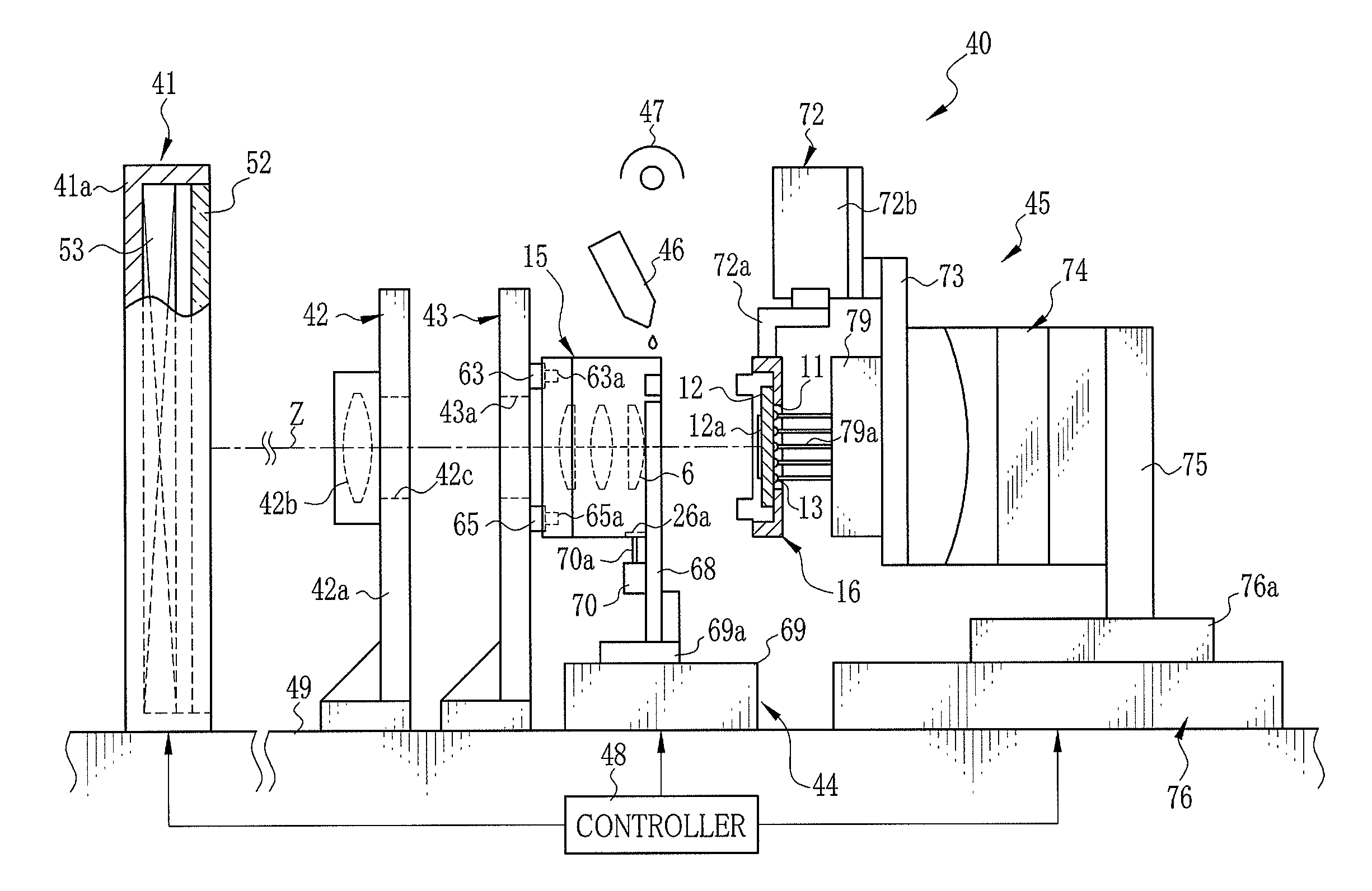
[0076]Next, the present invention is described. As shown in FIG. 5, a camera module manufacturing apparatus 40 is configured to adjust the position of the sensor unit 16 to the lens unit 15, and then fixe the sensor unit 16 to the lens unit 15. The camera module manufacturing apparatus 40 includes a chart unit 41, a light collecting unit 42, a lens positioning plate 43, a lens holding mechanism 44, a sensor shift mechanism 45, an adhesive supplier 46, an ultraviolet lamp 47 and a controller 48 controlling these components. All the components are disposed on a common platform 49.

[0077]The chart unit 41 is composed of an open-fronted boxy casing 41a, a measurement chart 52 fitted in the casing 41a, and a light source 53 incorporated in the casing 41a to illuminate the measurement chart 52 with parallel light beams from the back side. The measurement chart 52 is composed of, for example, a light diffusing plastic plate.

[0078]As shown in FIG. 6, the measurement chart 52 has a rectangula...

third embodiment

[0135]Although in the third embodiment the approximate curve AC is generated using the spline interpolation, a different interpolation method, such as a Bezier interpolation or an Nth polynomial interpolation may be used to generate the approximate curve AC. Furthermore, the approximate curve generating section 112 may be disposed outside the in-focus coordinate value obtaining circuit 110, although it is included in the in-focus coordinate value obtaining circuit 110 in the above embodiment.

[0136]Next, the fourth embodiment of the present invention is described. The fourth embodiment uses an in-focus coordinate value obtaining circuit 120 shown in FIG. 28 in place of the in-focus coordinate value obtaining circuit 87 shown in FIG. 8. Similar to the first embodiment, the in-focus coordinate value obtaining circuit 120 obtains the H-CTF values and the V-CTF values at plural measurement positions in the first to fifth imaging positions 89a-89e. Additionally, the in-focus coordinate va...

fourth embodiment

[0141]In the fourth embodiment, by way of contrast, the differences SB from the designated value 122 are calculated, and the measurement positions having the smallest difference SB are determined as the horizontal and vertical in-focus coordinate values. Since each in-focus coordinate value is shifted toward the designated value 122, adjusting the position of the sensor unit 16 based on the in-focus coordinate values serves to reduce the variation of the H-CTF values and the V-CTF values of the first to fifth imaging positions 89a-89e. As a result, the camera module 2 of this embodiment can produce images with an entirely uniform resolution to be perceived as good image quality.

[0142]The designated value 122 may be determined as needed according to a designed value and other design conditions of the taking lens 6. Additionally, the lowest value or an averaged value of each CTF value may be used as the designated value.

[0143]Although the designated value 122 is stored in the ROM 121 ...


PUM


Abstract

A lens unit and a sensor unit are held by a lens holding mechanism and a sensor shift mechanism. As the sensor unit is moved in a Z axis direction on a second slide stage, a chart image is captured with an image sensor through a taking lens so as to obtain in-focus coordinate values in at least five imaging positions on an imaging surface. An approximate imaging plane is calculated from the relative position of plural evaluation points which are defined by transforming the in-focus coordinate value of each imaging position in a three dimensional coordinate system. The second slide stage and a biaxial rotation stage adjust the position and tilt of the sensor unit so that the imaging surface overlaps with the approximate imaging plane.

Description

FIELD OF THE INVENTION[0001]The present invention relates to a method for adjusting position of an image sensor with respect to a taking lens, method and apparatus for manufacturing a camera module having a lens unit and a sensor unit, and the camera module.BACKGROUND OF THE INVENTION[0002]A camera module that includes a lens unit having a taking lens and a sensor unit having an image sensor such as CCD or CMOS is well known. The camera modules are incorporated in small electronic devices, such as cellular phones, and provide an image capture function.[0003]Conventionally, the camera modules are provided with an image sensor having as few pixels as one or two million. Since the low-pixel-number image sensors have a high aperture ratio, an image can be captured at appropriate resolution to the number of pixels without adjusting positions of the taking lens and the image sensor precisely. Recent camera modules, however, become to have an image sensor having as many pixels as three to ...

Claims


Application Information

Patent Timeline
Patent Type & Authority Applications(United States)
IPC IPC(8): H04N5/232G03B17/02H04N5/225H04N5/335
CPCH04N5/2253H04N17/002H04N5/2257H04N23/54H04N23/57
Inventor KIKUCHI, SHINICHINOJIMA, YOSHIO
Owner FUJIFILM CORP
Why Eureka
Try Eureka