Roll coating apparatus and method for producing a coated metal strip

a technology of coating apparatus and metal strip, which is applied in the direction of superimposed coating process, liquid/solution decomposition chemical coating, coating, etc., can solve the problems of uneven thickness of coating film in the width direction, inability to maintain uniform pressure, and difference in load, so as to maintain the overall rigidity of the stand and adjust the film thickness in a short period of tim

Active Publication Date: 2013-03-05
JFE STEEL CORP
View PDF7 Cites 0 Cited by
  • Summary
  • Abstract
  • Description
  • Claims
  • Application Information

AI Technical Summary

Benefits of technology

[0036]The roll coating apparatus of the present invention is capable of adequately adjusting the pressure force of a roll so that the pressure is uniform in the width direction of the roll, while at the same time maintaining the overall rigidity of stands that support the roll. As a result, by producing a coated metal strip using the roll coating apparatus of the present invention, it is possible to adjust the film thickness in a short period of time and to obtain a coated metal strip having a uniform film thickness in the width direction.

Problems solved by technology

In this kind of roll coating apparatus, the applicator roll 10 evenly presses the metal strip 9 over the entire width direction of the roll, and as long as each of the rolls 10, 20, press evenly over the entire width direction of the rolls, a uniform coating film thickness can be obtained in the width direction, however, when the pressure force on either the left or right end of the rolls 10, 20, 30 is strong (partial contact), or when the shape of the metal strip 9 itself is uneven in the width direction, it is not possible to maintain a uniform pressure in the width direction of the rolls, so the coating film thickness in the width direction becomes uneven.
However, normally, the rolls 10, 20, 30 are driven by separate motors, and due to the construction, the load of the joint section for transmitting that drive force is placed on the stand on the drive side, so the difference in load becomes a difference in resistance to movement by the left and right stands, and as a result there is a loss of balance between the left and right pressure force of rolls, so there is a possibility that the coating film thickness will become uneven in the width direction.
In such a case, by clearly knowing how the film thickness will change according to how much the left and right pressure is changed, it is possible to adjust the film thickness in a short period of time, however, fine adjustment is not possible with the calculated pressure setting, and actually in order to balance the left and right pressure force of the rolls, it is necessary to perform adjustment so that the left and right are within the desired film thickness range by repeatedly changing the left and right pressure a little at a time and checking the film thickness.
When doing this, as a method of measuring and checking the film thickness while online (line in operation) is a method of measuring the thickness of a water film that is not dry directly after coating and converting that thickness to a dry film thickness, however, the accuracy is poor, so in many cases, with the film in a dry state, the film thickness is converted by fluorescent X-ray analysis of the element, or by an infrared film thickness meter.
In order to do this, fine adjustment of the film thickness and measurement of the film thickness are repeated, however, during this time, a problem occurs in that areas where there is variation in the film thickness are produced, causing a decrease in yield.
A control method which measures the pressure load (pressure force) on the left and right of a roll using a load detection device (pressure detection device) such as a load cell, and minimizes the difference between the left and right pressure is widely used as a method for controlling the roll pressure (for example refer to patent document 6), however, in that case, as described above, there is a problem in that the force transmitted by the pressure on one side may be detected by the load detection device on the other side, and the pressure load on one side may affect the measurement value of the pressure force on the other side, thus the increased pressure force cannot be measured accurately, and the fine adjustment process described above for adjusting the film thickness (cycle of changing the pressure force→drying→measuring the film thickness) takes time.
Moreover, portions where there was deviation from the reference film thickness when adjusting the film thickness cannot be made into a product so there is a problem in that there is a decrease in yield.
In addition, there is a problem in that the faster the line speed is, these portions where there is deviation from the reference film thickness when adjusting the film thickness increase.

Method used


Image

  • Roll coating apparatus and method for producing a coated metal strip
  • Roll coating apparatus and method for producing a coated metal strip
  • Roll coating apparatus and method for producing a coated metal strip

Examples


example 1

[0072]A first example of the present invention will be explained below.

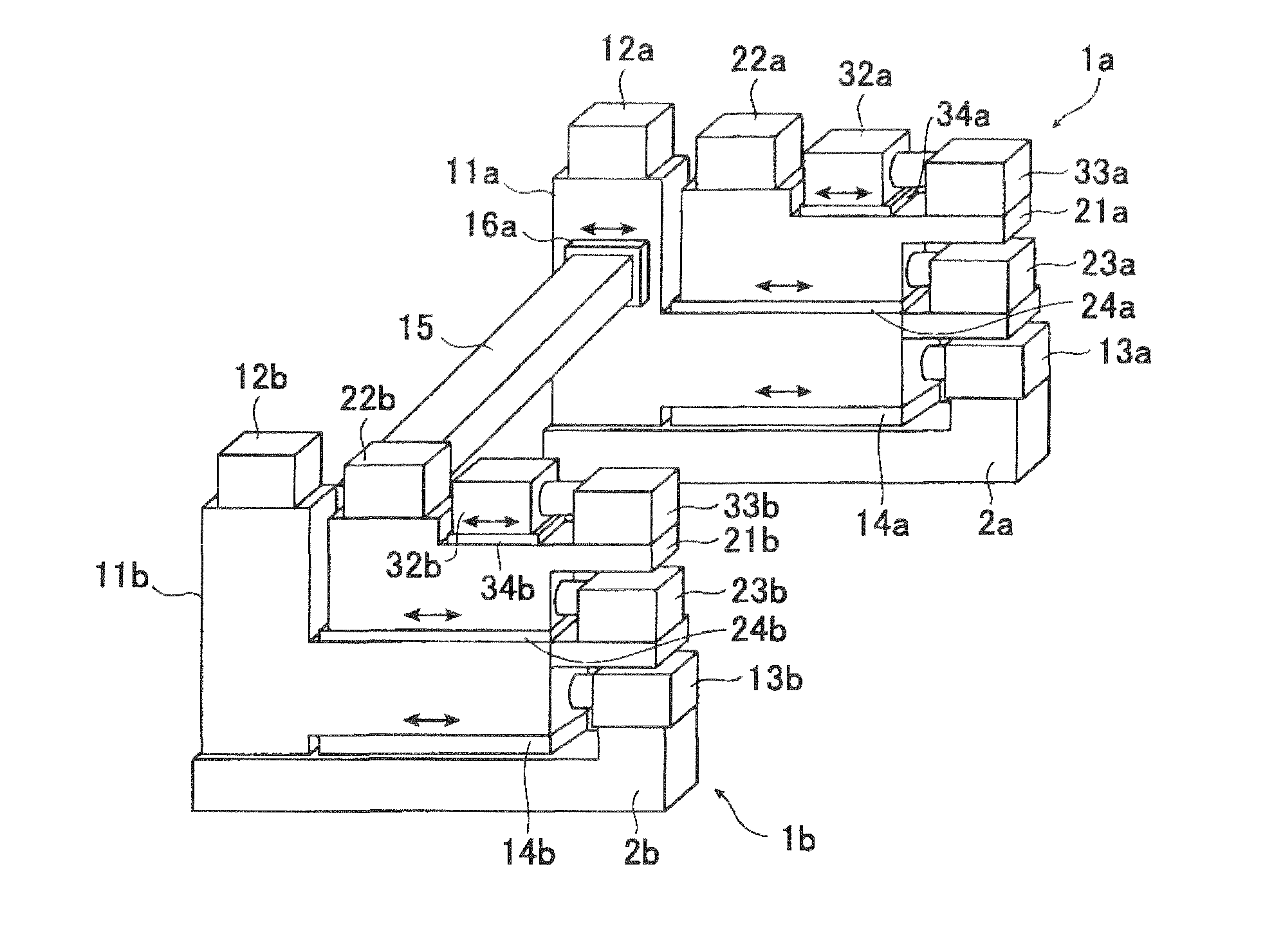
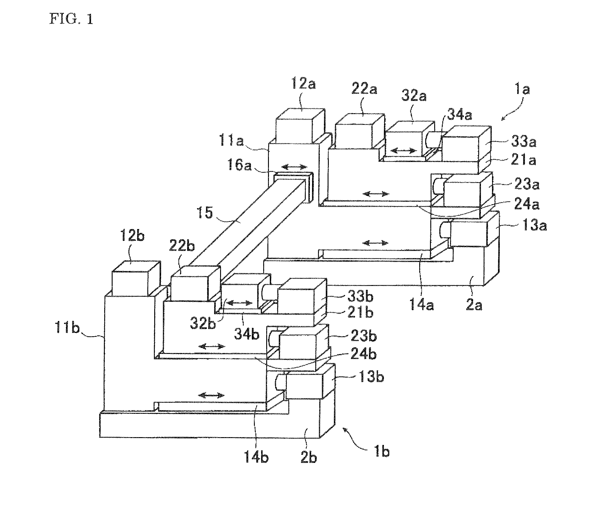
[0073]In this first example, as case 1, the pressure mechanisms 13a, 23a, 33a of the right stand 1a are put into operation, and when the applicator roll is pressed against the object being coated with a pressure of 100 kgf on only the side of the right stand 1a, the pressure load that was applied on the object being coated by the applicator roll was measured by a pressure load detection device that was provided in the left stand 1b. Similarly, as case 2, the pressure mechanisms 13b, 23b, 33b of the left stand 1b are put into operation, and when the applicator roll is pressed against the object being coated with a pressure of 100 kgf on only the side of the left stand 1a, the pressure load that was applied on the object being coated by the applicator roll was measured by a pressure load detection device that was provided in the right stand 1b.

[0074]When doing this, the 3-roll coating apparatus illustrated in FIG....

example 2

[0078]The 3-roll coating apparatus of the invention (FIG. 1, FIG. 2) and the conventional 3-roll coating apparatus (FIG. 6, FIG. 7) that were used in the first example, are used, and the film thickness was adjusted using the pressure control method illustrated in FIG. 5.

[0079]In other words, taking 1.0±0.2 μm to be the desired film thickness, the preset roll coater conditions were set according to the fluid density and line speed, and coating was begun, then after the coating dried, the film thickness was measured online at two locations in the width direction using a film thickness meter, and feedback control was performed to change and adjust the left and right pressure force between the coated object and applicator roll so that the difference in the film thickness at those two locations were within an allowable range. Moreover, by doing this, the time required for setting the film thickness at the two locations on the left and right to be within the range of the desired film thic...


PUM

PropertyMeasurementUnit
thicknessaaaaaaaaaa
pressureaaaaaaaaaa
thicknessaaaaaaaaaa

Abstract

There is provided a roll coating apparatus and method for producing a coated metal strip. The roll coating apparatus presses a roll against the surface of a metal strip and coats the metal strip with a coating fluid, and is capable of adequately adjusting the pressure force of the roll so that it is uniform in the width direction of the roll, while maintaining the overall rigidity of stands that support the roll. A connecting member 15 connects an applicator roll support unit 11a in a right stand 1a and an applicator roll support unit 11b in a left stand 1b, and a connecting member movement mechanism 16a is provided between the right end of the connecting member 15 and the applicator roll support unit 11a in the right stand 1a, making it possible for the connecting member 15 to move in the direction of pressure against the metal strip.

Description

[0001]This application is a U.S. National Phase Application under 35 USC 371 of International Application PCT / JP2009 / 065138 filed Aug. 25, 2009.FIELD OF THE INVENTION[0002]The present invention relates to a roll coating apparatus (roll coater) that coats the surface of a metal strip, and to a method for producing a coated metal strip.RELATED ART[0003]Various methods are known as a method for continuously coating a metal strip such as a steel plate or aluminum plate, however, when coating with a relatively thin film, a roll coating apparatus (roll coater) that presses a roll again the surface of the metal strip and applies a coating fluid is widely used. Typically, a plurality of rolls is arranged in the roll coating apparatus, with both ends of these rolls (hereafter, expressed as right and left (in the direction of advancement of the metal strip)) being supported by stands (left and right stands) by way of roll chocks that are equipped with bearings, and the thickness of the coatin...

Claims


Application Information

Patent Timeline
Patent Type & Authority Patents(United States)
IPC IPC(8): B05D1/28B05C1/06
CPCB05C1/0821B05C1/0834B05C1/083B05C1/08B05D1/28
Inventor KARIYASU, TAKAHIROMORIKAWA, MASAHIDE
Owner JFE STEEL CORP
Why Eureka
Try Eureka