Electrical connector with improved housing background of the invention

a technology of insulating housing and connector, which is applied in the direction of two-part coupling devices, coupling device connections, printed circuits, etc., can solve the problems of reducing the rigidity of the insulative housing at the same time, and not being advantageous to manufacturing, so as to achieve the effect of maintaining the rigidity of the insulative housing

Inactive Publication Date: 2011-07-26
HON HAI PRECISION IND CO LTD
View PDF26 Cites 25 Cited by
  • Summary
  • Abstract
  • Description
  • Claims
  • Application Information

AI Technical Summary

Benefits of technology

[0006]Accordingly, an object of the present invention is to provide an electrical connector adapted for the miniaturization trend and still keeping rigidity of the insulative housing.

Problems solved by technology

As the terminal grooves are running through the insulative housing along a vertical direction for allowing the terminals to be inserted thereinto directly from a bottom face of the insulative housing, which is benefit for reducing the height of the receptacle connector, while, if the height of the insulative housing is reduced, the rigidity of the insulative housing is simultaneously weakened and not advantageous for manufacturing.
There is also another problem, the U shaped contacting portion needs a deflectable space when mating with the plug connector, which ask for the insulative housing to increase its height, obviously, that is not the industry wanted.

Method used


Image

  • Electrical connector with improved housing background of the invention
  • Electrical connector with improved housing background of the invention
  • Electrical connector with improved housing background of the invention

Examples


Embodiment Construction

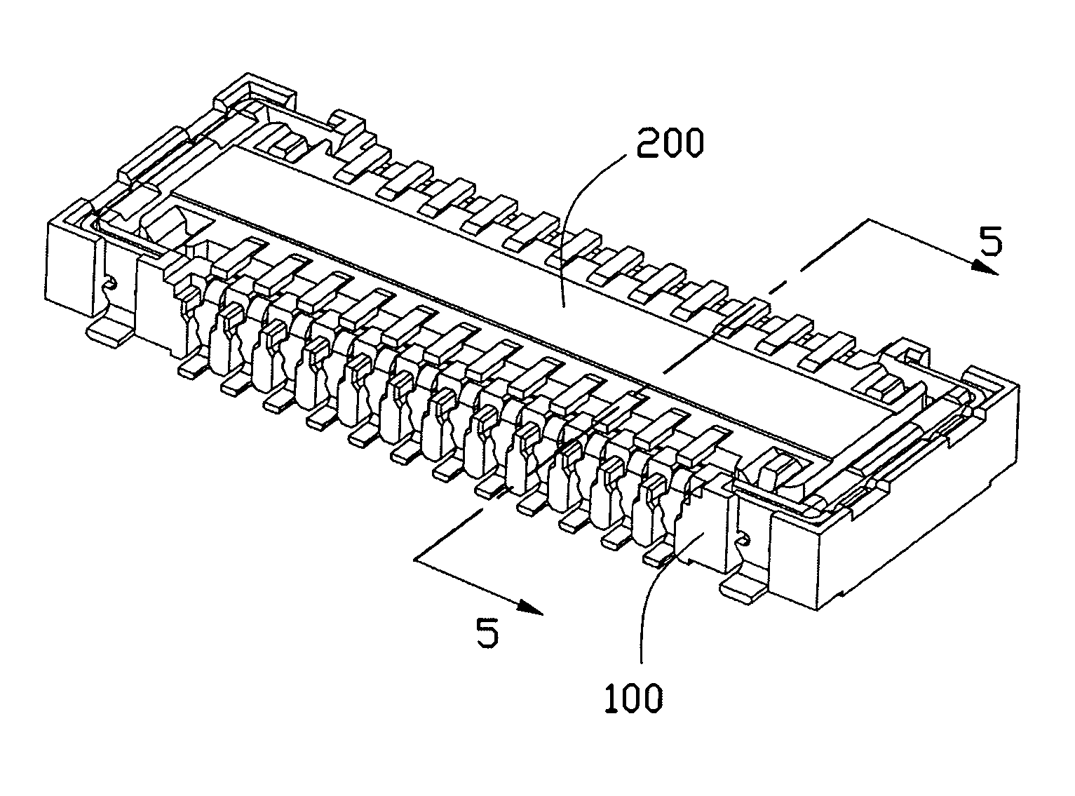
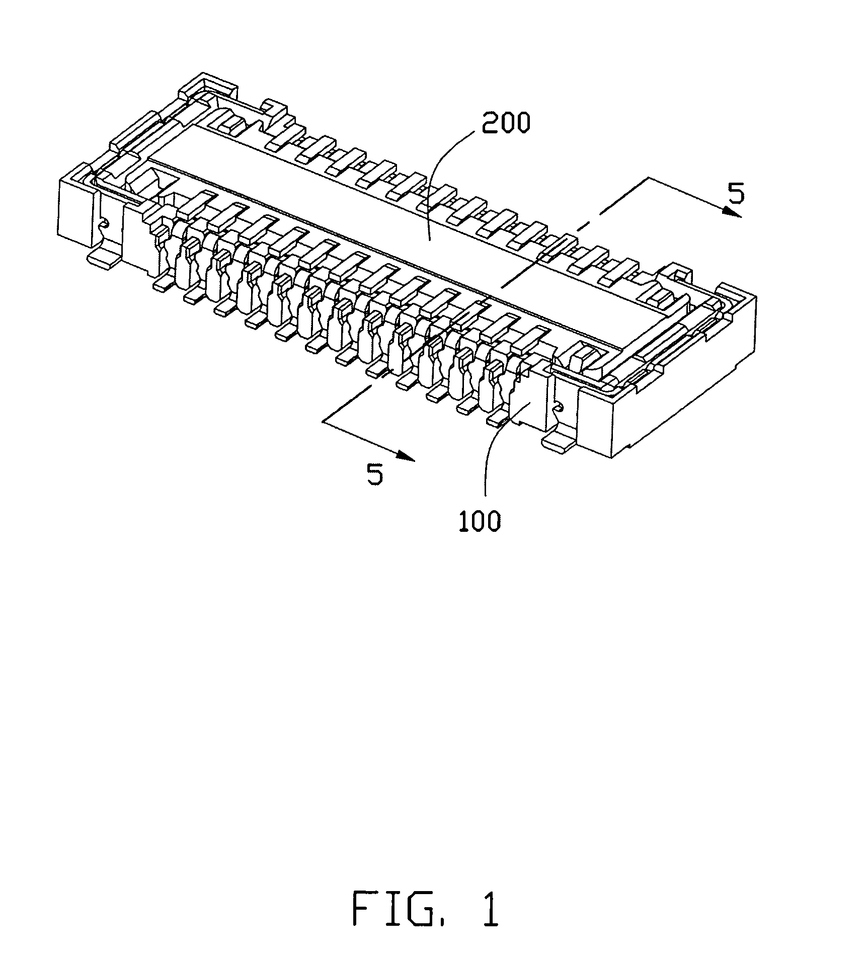
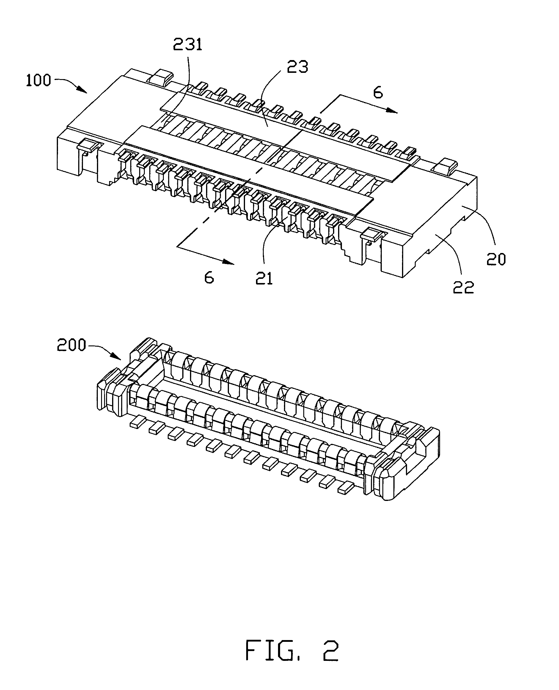
[0014]Reference will now be made to the drawing figures to describe a preferred embodiment of the present invention in detail. Referring to FIGS. 1 and 2, an electrical connector 100 made according to the preferred embodiment of the present invention is provided and mounted onto a printed circuit board (not shown) for mating with a plug connector 200.

[0015]Referring to FIGS. 2 and 3, the electrical connector 100 comprises an elongated housing 20, a plurality of conductive contacts 30 retained in the housing 20 and a pair of retaining plates 40 assembled on opposite ends of the housing 20. The housing 20 has a pair of opposite side walls 21 extending along a longitudinal direction, a pair of end walls 22 connecting with the side walls 21 and a bottom wall 23 located under said side walls 21 and end walls 22 thereby defining a mating cavity 25 therebetween for receiving said plug connector 200. A plurality of terminal grooves 26 are defined in said mating cavity 25 for receiving said ...


PUM


Abstract

An electrical connector is provided and includes a housing having a pair of side walls defining a plurality of terminal grooves therein and a bottom wall connecting with said side walls and defining a top face facing upward. A plurality of terminals are received in said terminal grooves, each comprising a retaining portion and a contacting portion extending from the retaining portion, said contacting portion having a connecting portion cantilevered above said top face. The bottom wall defines a plurality of through holes running therethrough along a vertical direction and facing to an end of the connecting portion which is far away from the retaining portion, and said top face of the bottom wall extends slantwise from the through hole to the side walls therefore places adjacent to the through hole are lower than those adjacent to the side walls in said vertical direction.

Description

BACKGROUND OF THE INVENTION[0001]1. Field of the Invention[0002]The present invention relates to an electrical connector, and more particularly to an electrical connector having a housing for securing a plurality of terminals therein.[0003]2. Description of the Related Art[0004]TW Patent No. M302787 issued to ENTERY INDUSTRIAL CO., LTD. on Dec. 11, 2006 discloses a board to board connector assembly including a receptacle connector and a plug connector. The receptacle connector includes an insulative housing defining a receiving room therein for receiving said plug connector and a tongue plate with a plurality of terminal grooves therein disposed in, said receiving room. A plurality of terminals are secured in said terminal grooves, each of which comprises a retaining portion fixed in the insulative housing, an U shaped contacting portion extending from the retaining portion and disposed in said receiving room, and a solder portion projecting out of the insulative housing.[0005]As th...

Claims


Application Information

Patent Timeline
Patent Type & Authority Patents(United States)
IPC IPC(8): H01R24/00
CPCH01R12/57H01R12/714
Inventor WU, CHUN-KWAN
Owner HON HAI PRECISION IND CO LTD
Why Eureka
Try Eureka