Liquid ejection head, liquid ejection apparatus, and method for fabricating liquid ejection head

a liquid ejection head and liquid ejection technology, which is applied in the direction of printing, way cleaning, construction, etc., can solve the problems of reducing the resolution preventing the improvement of the print quality, and the ink deposited in the area cannot be completely removed, so as to achieve simple and efficient ejection, improve the quality of the print image, and reduce the thickness of the nozzle sheet

Inactive Publication Date: 2006-07-13
SONY CORP
View PDF3 Cites 25 Cited by
  • Summary
  • Abstract
  • Description
  • Claims
  • Application Information

AI Technical Summary

Benefits of technology

[0024] Accordingly, the thickness of the nozzle sheet 117 in only an area in the vicinity of the nozzle 118 may be reduced to largely deflect the ejection direction of an ink droplet while maintaining the rigidity of the nozzle sheet 117. That is, in order to prevent the deformation of the nozzle sheet 117 due to ejection pressure of the heating element 113 or the vibration caused by paper feed during print time, the nozzle sheet 117 having a sufficient thickness is employed. Only the area of the nozzle sheet 117 in the vicinity of the nozzle 118 has a thickness corresponding to the length of the nozzles 118, and the other area of the nozzle sheet 117 is reduced in thickness.
[0039] According to a method for fabricating a liquid ejection head of the above-described embodiments, a liquid ejection head in which the nozzle is positioned at the bottom of a depression of a liquid ejection member and the interior angle of the bottom corner of the depression is greater than 90 degrees can easily be fabricated. Accordingly, a liquid ejection head that improves the print image quality while maintaining the rigidity of a nozzle sheet can easily be fabricated.

Problems solved by technology

Consequently, the resolution of a print image is reduced, thereby preventing the improvement of the print quality.
Also, the ink deposited to the area cannot be completely removed even when Japanese Unexamined Patent Application Publication No. 2001-1523 is applied.
However, this wiping mechanism cannot wipe the area of the nozzle sheet 117 having a small thickness (i.e., depression area).

Method used


Image

  • Liquid ejection head, liquid ejection apparatus, and method for fabricating liquid ejection head
  • Liquid ejection head, liquid ejection apparatus, and method for fabricating liquid ejection head
  • Liquid ejection head, liquid ejection apparatus, and method for fabricating liquid ejection head

Examples


first exemplary embodiment

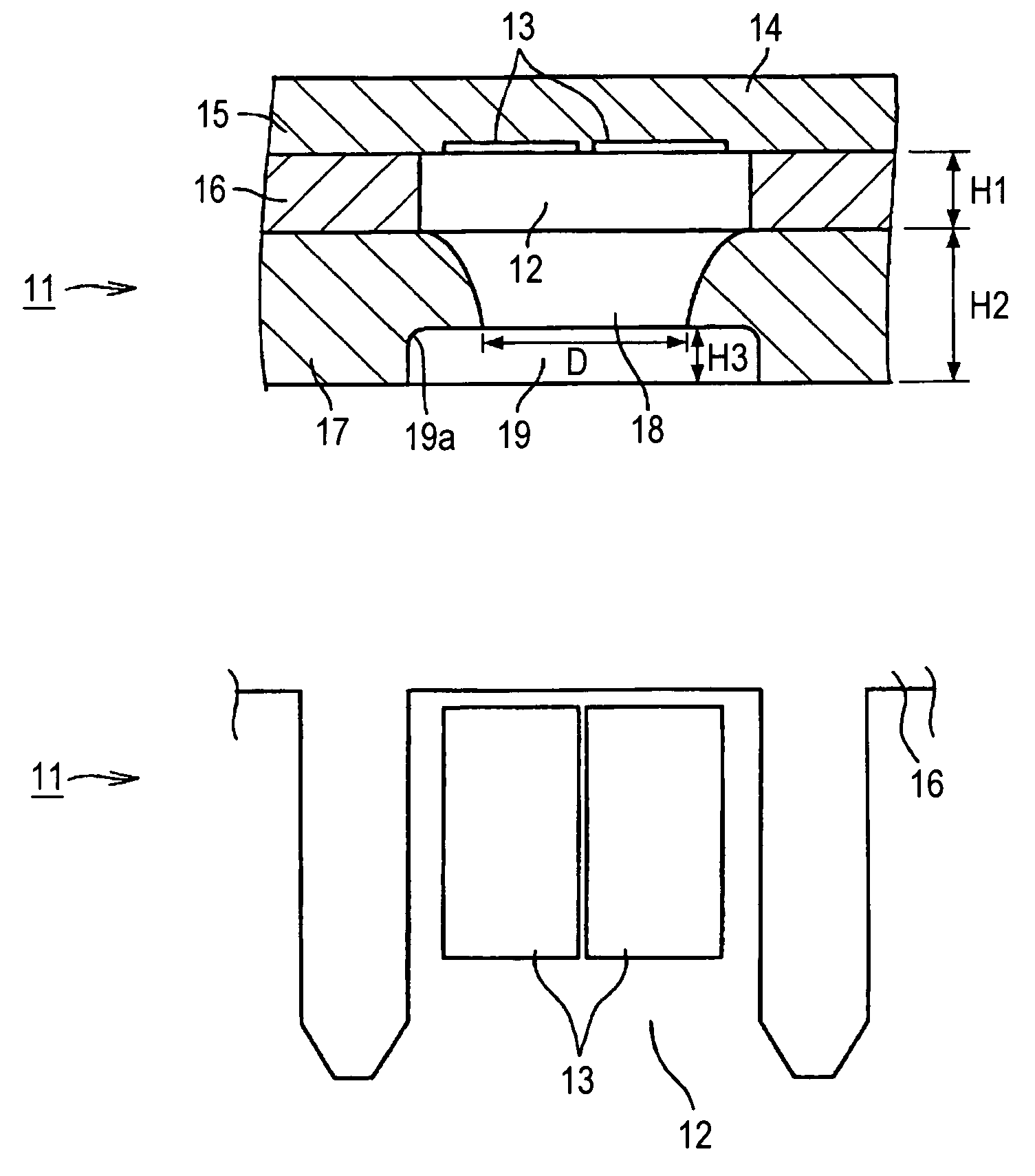
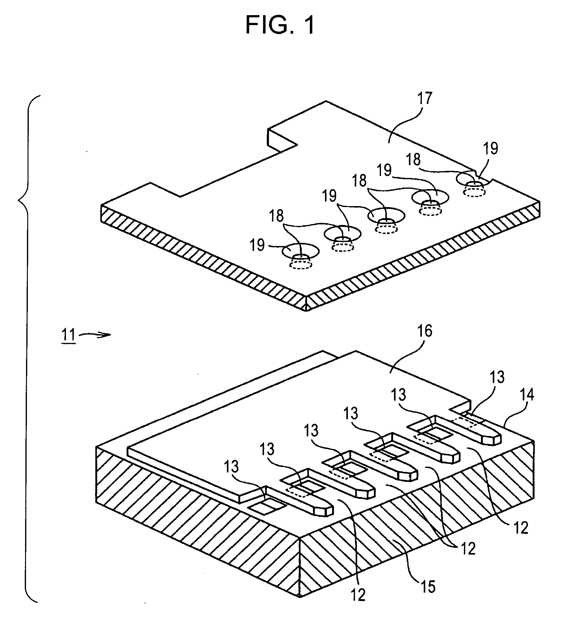
[0056]FIG. 1 is an exploded perspective view of the printer head 11 according to the first embodiment. In FIG. 1, a nozzle sheet 17 to be bonded to a barrier layer 16 is exploded. For the sake of convenience of description, the printer head 11 is shown upside-down relative to the orientation typically used for the real printer head 11.

[0057] As shown in FIG. 1, the printer head 11 according to the first embodiment includes the substrate member 14 having the heating element 13, the barrier layer 16 which corresponds to a liquid chamber forming member to form the ink chamber 12, and the nozzle sheet 17 which includes a nozzle 18 and which corresponds to a liquid ejection member. That is, the nozzle sheet 17 is bonded to the substrate member 14 with the barrier layer 16 therebetween.

[0058] The substrate member 14 includes the semiconductor substrate 15 and the heating element 13. That is, the heating element 13 is formed on a surface (top surface in FIG. 1) of the semiconductor subst...

second exemplary embodiment

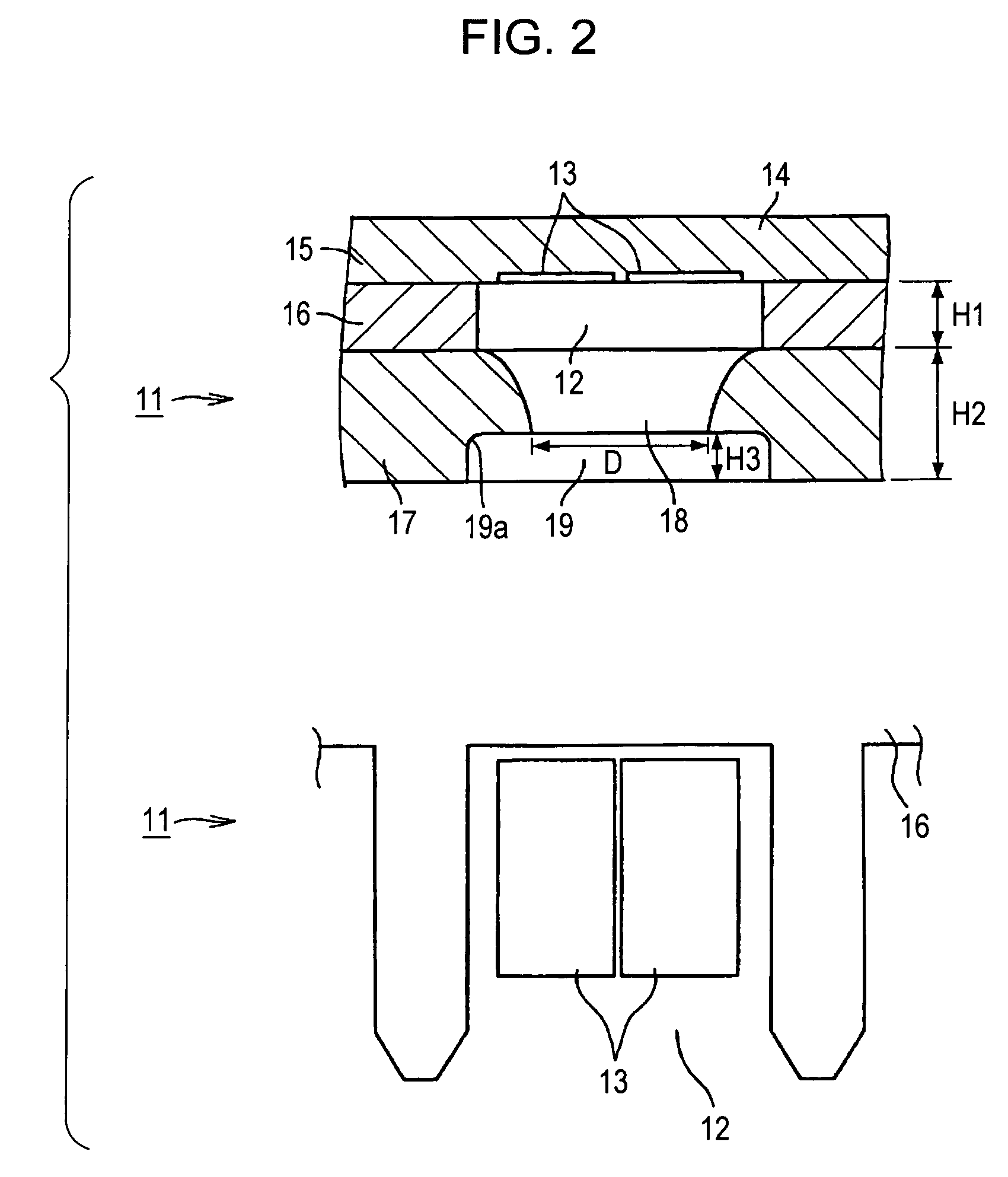
[0100]FIG. 8 is a partial sectional view of a depression 19 of a nozzle sheet 17 in a printer head 11 according to a second exemplary embodiment.

[0101] As shown in FIG. 8, in the second embodiment, a bottom corner 19a of the depression 19 formed on the front surface of the nozzle sheet 17 has a slope shape (a sloping surface), which is greater than 90 degrees.

[0102] Like the first embodiment, in the printer head 11 according to the second embodiment, the slope of the bottom corner 19a of the depression 19 prevents ink from spreading in a direction of the surface tension H and an area that generates the adhesive force M is reduced. Accordingly, as shown in FIG. 8, ink deposited to the interior of the depression 19 is drawn back into the nozzle 18 without being cut out, and the ink deposited to the interior of the depression 19 is returned to inside the nozzle 18. As a result, the accumulation of the ink in the depression 19 can be prevented, and therefore, the print quality is not ...

third exemplary embodiment

[0103] Like the printer head 11 according to the first embodiment shown in FIG. 7, in a printer head 11 according to a third embodiment, the bottom corner 19a of the depression 19 has a rounded shape (curved surface). In the third embodiment, a surface of the nozzle sheet 17 including the depression 19 is treated with a water-repellent finish. Accordingly, the spreading force of the ink in a direction of the surface tension H is further decreased, and an area that generates the adhesive force M is further reduced. Also, a horizontal component of the adhesive force M is further decreased. As a result, the accumulation of the ink in the depression 19 can be prevented, and therefore, the print quality is not degraded.

[0104] As described above, in the printer head 11 according to this embodiment, the depression 19 having an opening width greater than the nozzle 18 is formed on the surface of the nozzle sheet 17. Additionally, the bottom corner 19a of the depression 19 is greater than 9...


PUM

PropertyMeasurementUnit
interior angleaaaaaaaaaa
distanceaaaaaaaaaa
deflection widthaaaaaaaaaa

Abstract

A liquid ejection head includes a liquid chamber configured to contain liquid to be ejected from a nozzle, a liquid ejection member including the nozzle, and an energy generating element configured to provide energy to the liquid contained in the liquid chamber. The energy generating element ejects the liquid contained in the liquid chamber from the nozzle as a liquid droplet. A depression is formed on a surface of the liquid ejection member around the nozzle such that an opening of the depression has a width greater than a width of an opening of the nozzle and the nozzle is positioned at the bottom of the depression. The interior angle of the bottom corner of the depression is determined to be greater than 90 degrees.

Description

CROSS REFERENCES TO RELATED APPLICATIONS [0001] The present invention contains subject matter related to Japanese Patent Application JP 2005-004606 filed in the Japanese Patent Office on Jan. 12, 2005, the entire contents of which are incorporated herein by reference. BACKGROUND OF THE INVENTION [0002] 1. Field of the Invention [0003] The present invention relates to a liquid ejection head that ejects liquid contained in a liquid chamber from a nozzle as liquid droplets, a liquid ejection apparatus, and a method for fabricating the liquid ejection head. In particular, the present invention relates to a technology that improves print quality while maintaining the rigidity of a nozzle sheet including the nozzle. [0004] 2. Description of the Related Art [0005] A liquid ejection head that ejects liquid from a nozzle using an energy generating element has become widespread. For example, printer heads of inkjet printers are of this type, in which a pressure is applied to ink contained in ...

Claims


Application Information

Patent Timeline
Patent Type & Authority Applications(United States)
IPC IPC(8): B41J2/16
CPCB41J2/14056B41J2/1433B41J2/162B41J2/1625B41J2/1628Y10T29/49401B41J2/1639B41J2/1645B41J2/1646B41J2002/14387B41J2/1631E01H5/066
Inventor TOMITA, MANABUUSHINOHAMA, IWAOKAYABA, SHINJIEGUCHI, TAKEO
Owner SONY CORP
Why Eureka
Try Eureka