Orthodontic bracket and clip release tool

a technology for orthodontic brackets and tools, applied in dental tools, dental surgery, medical science, etc., can solve the problems of clip deformation, easy deformation of clips, and overloaded load of clips

Inactive Publication Date: 2009-03-19
TOMY CHOFU TOKIOTOKYO JP
View PDF22 Cites 25 Cited by
  • Summary
  • Abstract
  • Description
  • Claims
  • Application Information

AI Technical Summary

Benefits of technology

[0020]In the thus structured orthodontic bracket, the clip is provided at the upper end part thereof with the recess portion which enables to catch the clip release tool for releasing the clip. The position catching the clip release tool is formed to be the recess, so that it is not required to open a hole for the clip to pass through in the thickness direction. Thus, although the clip is substantially U-shaped and narrow in width, it keeps rigidity and can secure spring force to press down the arch wire.
[0040]Pressing the clip with the second projection, when releasing the clip, the clip is prevented from turning up and deformation.

Problems solved by technology

But, when releasing the clip by the bar-like tool inserted in the hole of the clip, it is necessary to work the bar-like tool as a lever, and so an exceeding load is effected on the clip.
Therefore, when releasing the clip by the bar-like tool, the clip is often deformed.
Further, since the hole into which the bar-like tool is inserted is formed at about center of the clip, a spring property of the clip is spoiled to reduce force pressing down the arch wire, and besides a problem arises that the clip is easily deformed owing to concentration of stress.

Method used


Image

  • Orthodontic bracket and clip release tool
  • Orthodontic bracket and clip release tool
  • Orthodontic bracket and clip release tool

Examples


first embodiment

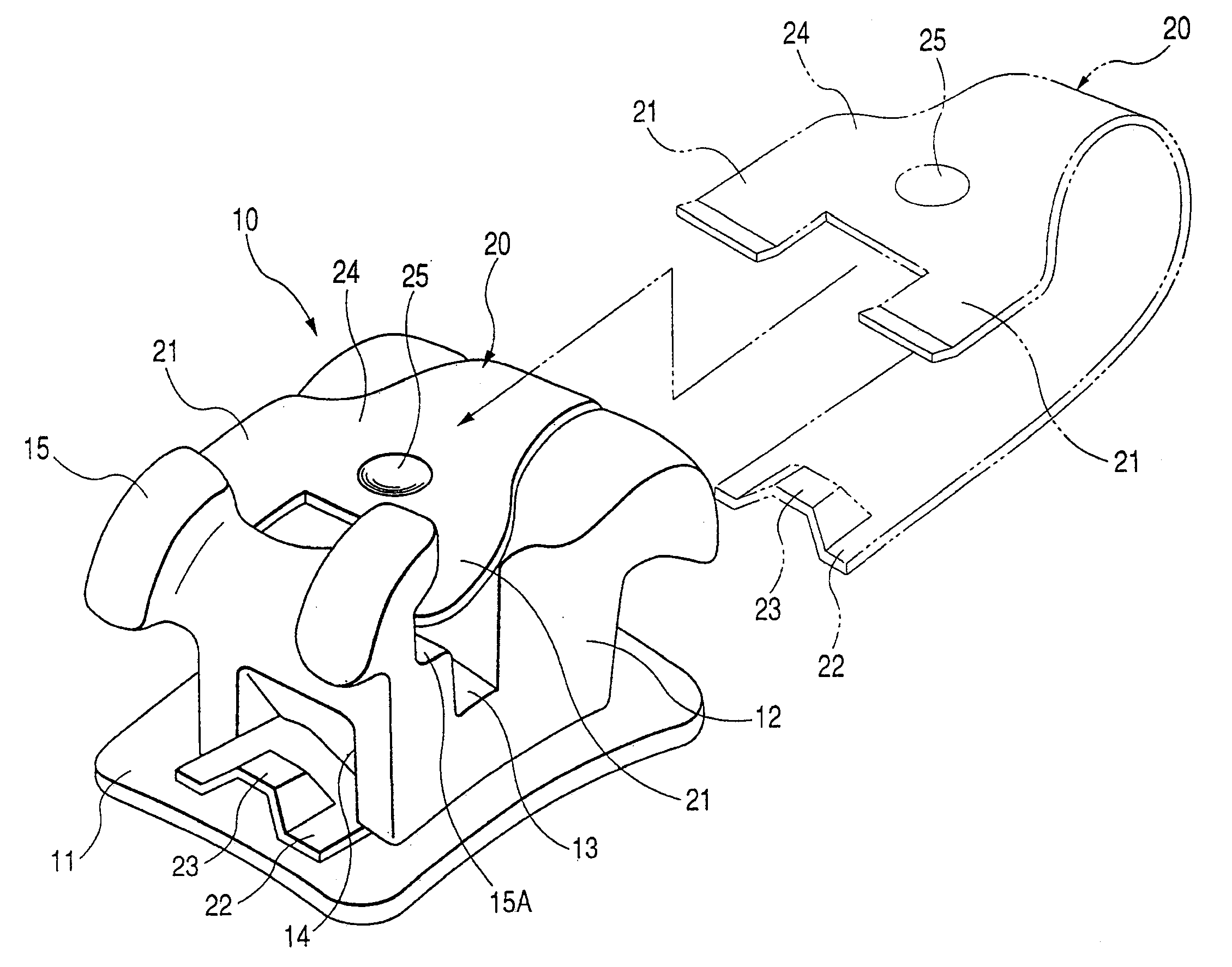
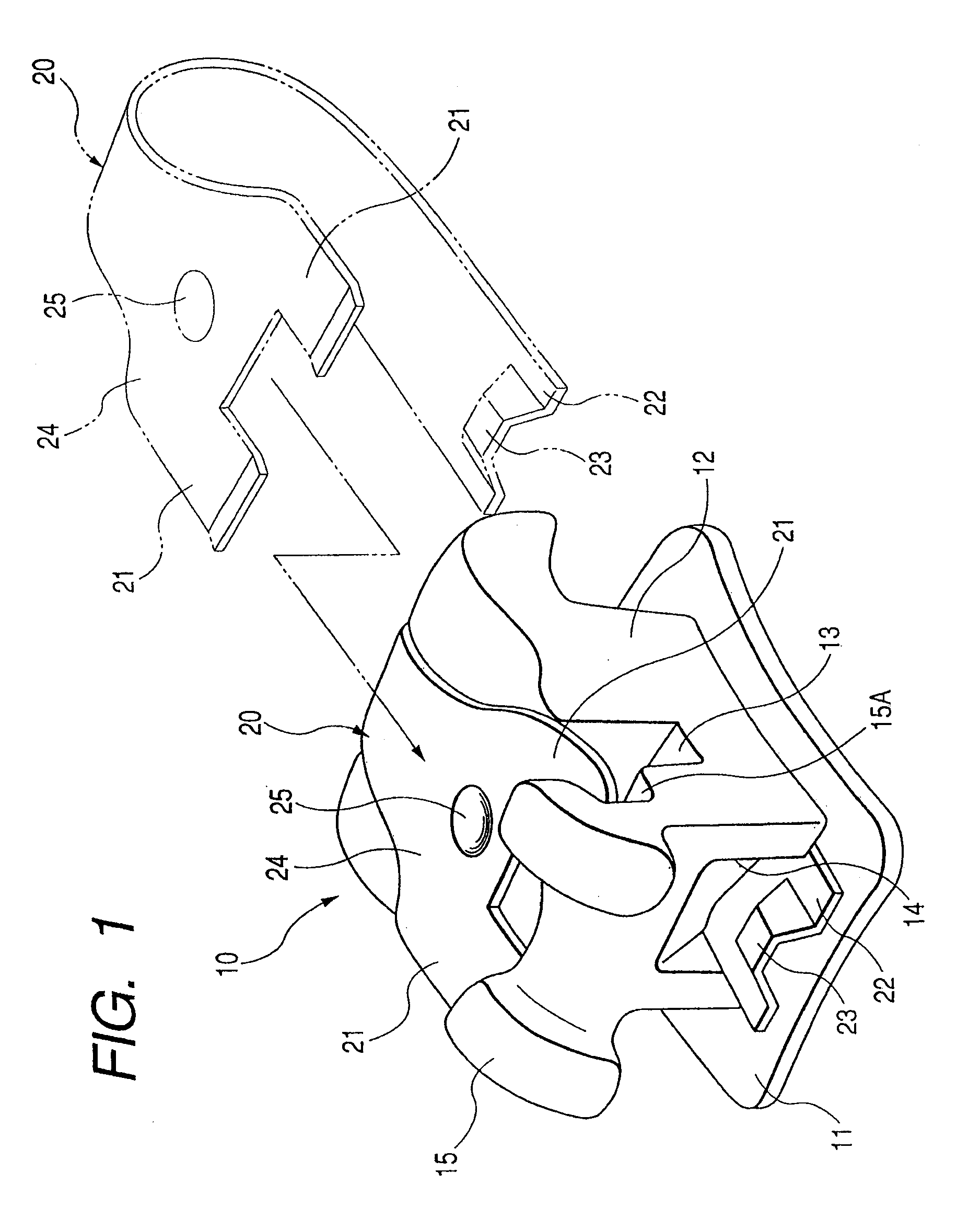
[0076]As shown in FIG. 1, an orthodontic bracket 10 as the invention comprises a base 11, a bracket main body 12, an arch wire slot 13, a guide portion 14, and a substantially belt-like clip 20. The base 11 is firmly attachable directly or indirectly to teeth surfaces. The bracket main body 12 is equipped on one side of the base 11. The arch wire slot 13 is shaped in groove in the bracket main body 12. The guide portion 14 is formed in at least one of the bracket main body and the base, and along a tooth axial direction crossing with the arch wire slot 13. The substantially belt-like clip 20 is guided by the guide portion 14.

[0077]The arch wire slot 13 is formed along the mesiodistal direction of the bracket main body 12.

[0078]In the orthodontic bracket 10, the clip 20 is curved substantially in U-shape as covering at least one part of an opposite side to the base in the arch wire slot 13. A pair of catching end portions 21 are provided at an upper end part along length of the clip ...

third embodiment

[0124]Next, a third embodiment will be referred to.

[0125]As shown in FIG. 12, a clip 50 as the third embodiment of the invention is different from the clip 20 of the first embodiment only in that the clip 50 has, as the recess portion, a cut-and-rising portion 51 rising in a direction separating from the bracket main body 12 (see FIG. 1) along the thickness, and other structures are the same as those of the first embodiment.

[0126]The cut-and-rising portion 51 is provided substantially in a half-spherical dome shape at an end part 52 of the clip 50.

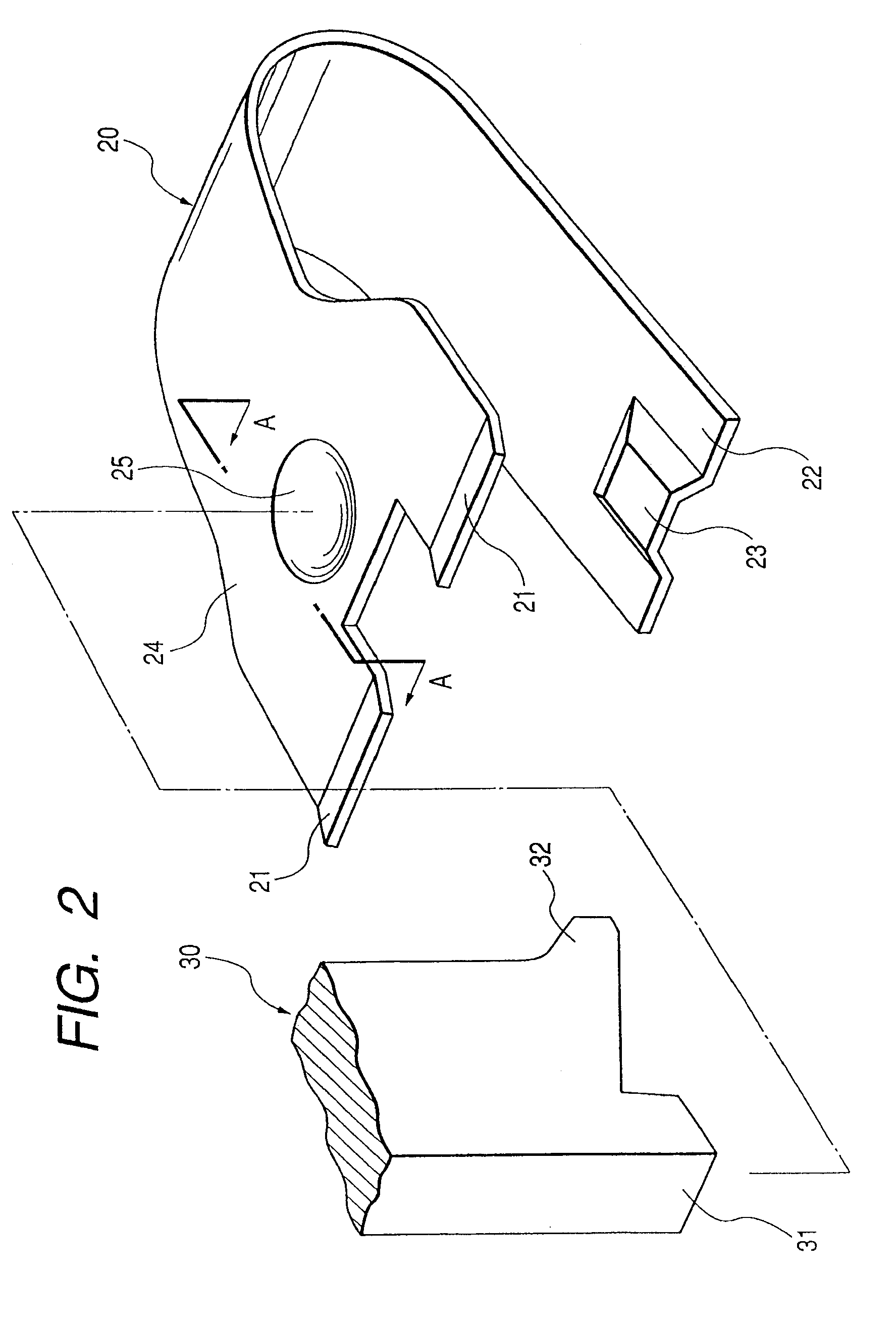
[0127]If the clip release tool 30 is moved under a condition of contacting the heel portion 31 (see FIG. 2) to the cut-and-rising portion 51, the clip 50 can be released together with the clip release tool 30.

[0128]In the clip 50 of the third embodiment, the same effect as that of the clip 20 of the first embodiment can be also obtained.

fourth embodiment

[0129]Next, a fourth embodiment will be referred to.

[0130]As shown in FIG. 13, a clip 60 as the fourth embodiment of the invention is different from the clip 20 of the first embodiment only in that the clip 60 has, as the recess portion, a cut-and-rising portion 61 raising in a direction separating from the bracket main body 12 (see FIG. 1) along the thickness, and other structures are the same as those of the first embodiment.

[0131]The cut-and-rising portion 61 is provided substantially in a half-spherical dome shape at an end part 62 of the clip 60, and a cutout portion 64 substantially in V-shape is provided in a flat end part 63 of the cut-and-rising portion 61.

[0132]If the clip release tool 30 is moved under a condition of contacting the heel portion 31 (see FIG. 2) to the cut-and-rising portion 61, the clip 60 can be released together with the clip release tool 30.

[0133]In this case, since the substantially V-shaped cutout 64 is provided in the flat end part 63 of the cut-and-...


PUM


Abstract

A clip release tool with a first and second projection, for releasing a clip from a main bracket body of an orthodontic bracket while regulating movement or deformation of the clip, and a related method, and a method of attaching a clip to an orthodontic bracket main body using a clip release tool.

Description

[0001]This application is a Continuation-In-Part of pending U.S. patent application Ser. No. 10 / 730,268, filed Dec. 9, 2003, and entitled “ORTHODONTIC BRACKET AND CLIP RELEASE TOOL”, which claims the benefit of U.S. Provisional Application No. 60 / 431,693, filed Dec. 9, 2002. This application also claims priority from Japanese Patent Application No. 2008-122879, filed on May 9, 2008 in the Japanese Patent Office. The disclosures of each of these applications are incorporated herein in their entirety by reference.BACKGROUND OF THE INVENTION[0002]1. Field of the Invention[0003]The present invention relates to an orthodontic bracket and a clip release tool, and in particular, for correcting irregular teeth rows or twisted teeth, relates to an orthodontic bracket and a clip release tool.[0004]2. Description of the Related Art[0005]In general, the orthodontic bracket has been used for correcting teeth rows. As to the orthodontic bracket, a base thereof is provided with a bracket main body...

Claims


Application Information

Patent Timeline
Patent Type & Authority Applications(United States)
IPC IPC(8): A61C3/00A61C7/14
CPCA61C7/287A61C7/02
Inventor OPIN, PERRYKATAYOSE, SHINGOENDO, KOUSEIORIKASA, MASAAKIKAWASAKI, TOMOHIKO
Owner TOMY CHOFU TOKIOTOKYO JP
Why Eureka
Try Eureka