Multiocular Intraocular Lens Systems

a multi-ocular, intraocular technology, applied in optics, medical science, instruments, etc., can solve the problems of bifocal intraocular lenses, only about 40% of available light in bifocal images, and the ability of the eye to function properly, so as to increase the amplitude or diopter of accommodation

Inactive Publication Date: 2008-02-21
C& C VISION INT
View PDF86 Cites 58 Cited by
  • Summary
  • Abstract
  • Description
  • Claims
  • Application Information

AI Technical Summary

Benefits of technology

[0011]After surgical implantation of the accommodating intraocular lens in the capsular bag of the eye, active ectodermal cells on the posterior side of the anterior capsule rim of the bag cause fusion of the rim to the elastic posterior capsule of the bag by fibrosis. This fibrosis occurs about the lens extended portions in such a way that these extended portions are effectively “shrink-wrapped” by the fibrous tissue in such a way as to form radial pockets in the fibrous tissue which contain the extended portions with their outer ends positioned within the outer cul-de-sac of the capsular bag. In this case, the lens is thereby fixated within the capsular bag with the lens optic aligned with the anterior capsule opening in the bag. The anterior capsule rim shrinks during fibrosis, and this shrinkage combined with shrink-wrapping of the extended portions causes some radial compression of the lens in a manner which tends to move the lens optical system relative to the outer ends of the extended portions posteriorly along the axis of the eye. The fibrosed, leather-like anterior capsule rim prevents anterior movement of the optic and urges the optic rearwardly during fibrosis. Accordingly, fibrosis induced movement of the optic system occurs posteriorly to a distant vision position during the healing process in which either or both the optic and the inner ends of the extended portions press rearwardly against the elastic posterior capsule of the capsular bag and stretch this posterior capsule rearwardly.
[0013]According to another important aspect of this invention, the extended portions of a presently preferred lens embodiment can be generally T-shaped haptics each including a haptic plate and a pair of relatively slender resiliently flexible fixation fingers at the outer end of the haptic plate. In their normal unstressed state, the two fixation fingers at the outer end of each haptic plate extend laterally outward from opposite edges of the respective haptic plate in the plane of the plate and substantially flush with the radially outer end edge of the plate to form the horizontal “crossbar” of the haptic T-shape. The radially outer end edges of the haptic plates are circularly curved about the central axis of the lens optical system to substantially equal radii closely approximating the radius of the interior perimeter of the capsular bag when the ciliary muscle of the eye is relaxed. During implantation of the lens in the bag, the inner perimetrical wall of the bag deflects the haptic fingers generally radially inward from their normal unstressed positions to arcuate bent configurations in which the radially outer edges of the fingers and the curved outer end edges of the respective haptic plates conform approximately to a common circular curvature closely approximating the curvature of the inner perimetrical wall of the bag. The outer T-ends of the haptics then press lightly against the perimetrical bag wall and are fixated within the bag perimeter during fibrosis to accurately center the implanted lens in the bag with the lens optical system aligned with the anterior capsule opening in the bag.
[0014]The haptic plates of certain described lens embodiments are narrower in width than the optic diameter. These relatively narrow plates of the haptics flex or pivot relatively easily to aid the accommodating action of the lens and form haptic pockets of maximum length in the fibrosed capsular bag between the haptic fingers and the optic which maximize the accommodation movement of the lens optic. The haptics can slide radially in the capsular bag pockets during contraction of the ciliary muscle to enable forward movement of the optical system for vision accommodation.
[0016]Presently preferred accommodating intraocular lenses of the invention are described. These preferred lenses comprise two optics integrally separated from each other by a fixed space, are generally T-shaped, flexibly hinged haptics and optics whose posterior portions provide most of the optical power of the optics. These optics cooperate with the anteriorly biased configurations of the lenses to increase accommodation amplitude or diopters of accommodation.

Problems solved by technology

The human eye is subject to a variety of disorders which degrade or totally destroy the ability of the eye to function properly.
Bifocal intraocular lenses, however, suffer from the disadvantage that each bifocal image represents only about 40% of the available light, and a remaining 20% of the light is lost in scatter.

Method used


Image

  • Multiocular Intraocular Lens Systems
  • Multiocular Intraocular Lens Systems
  • Multiocular Intraocular Lens Systems

Examples


Embodiment Construction

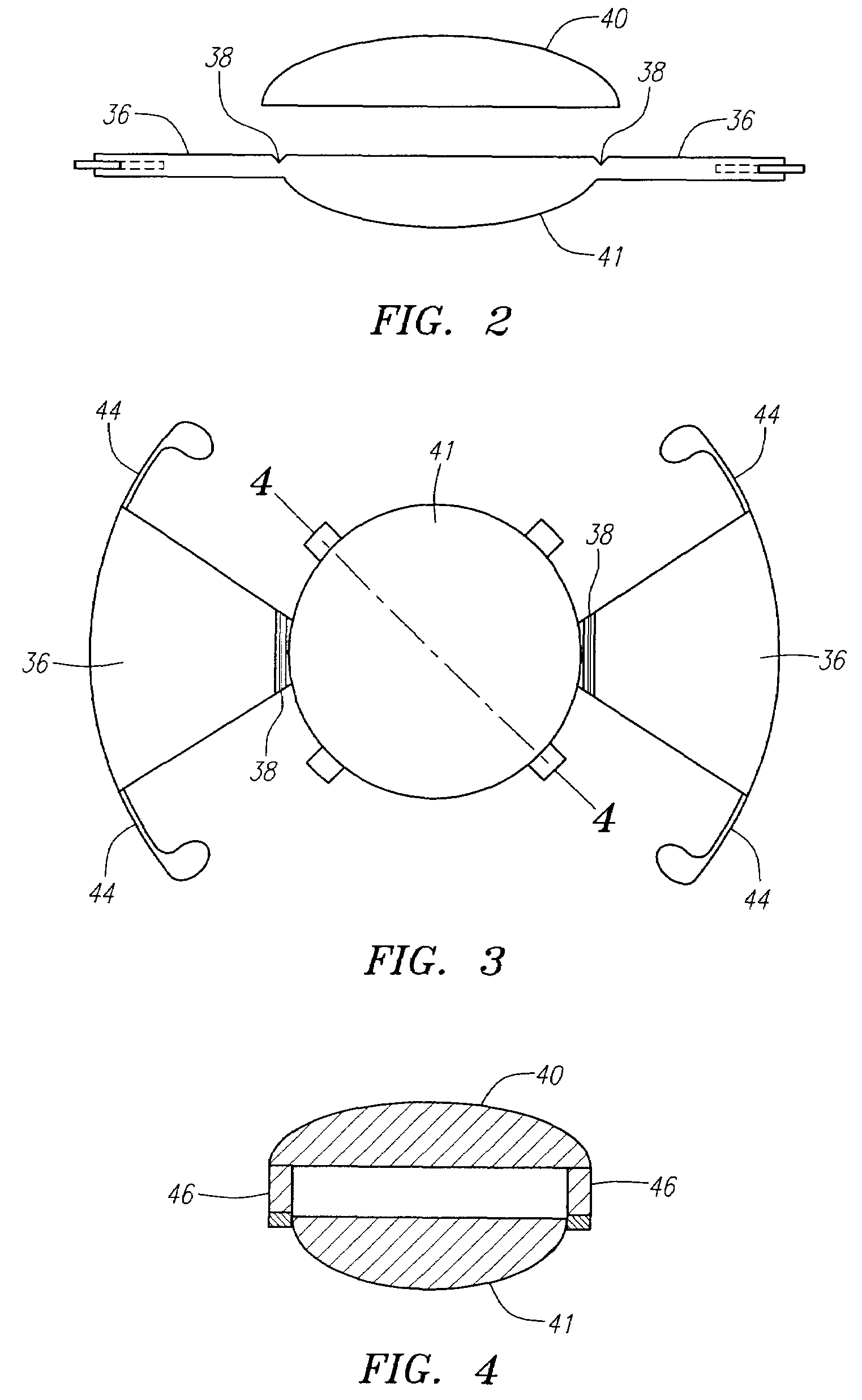
[0034]The lens system comprises two optics fused together, one in front of the other, as will be further explained beginning with FIG. 1 below. T-shaped extended portions or plate haptics 36 extend from diametrically opposite edges of the optic. These haptics include haptic members or plates 36 proper having inner ends joined one or other of the optics and opposite outer free ends and lateral fixation fingers at their outer ends. The haptic plates 36 may be longitudinally tapered so as to narrow or widen in width toward their ends or may be wider in their periphery and narrower adjacent to the optic. The optical system 34 is movable anteriorly and posteriorly relative to the haptics 36. The preferred lens embodiment illustrated is constructed of a resilient semi-rigid material and has flexible hinges 38 which join the inner ends of the haptic plates 36 to one of the optics. The haptics are relatively rigid and are flexible about the hinges anteriorly and posteriorly relative to the ...


PUM


Abstract

An accommodating intraocular lens having anteriorly and posteriorly movable extended portions, such as T-shaped haptics, extending from a central optic to be implanted within a human eye, and a second optic spaced from the posterior optic. The first optic is intended to be implanted in the capsular bag, and the second optic may be located in the capsular bag, in the sulcus, or in the anterior chamber. The second optic can be spaced from and fixed to the first optic and this lens assembly implanted in the capsular bag.

Description

[0001]This application claims the benefit of U.S. Provisional Application No. 60 / 822,475 filed Aug. 15, 2006, which applications are incorporated herein by reference.BACKGROUND OF THE INVENTION[0002]This invention relates generally to intraocular lenses to be implanted within the human eye formed by evacuation of the crystalline matrix from the natural lens of the eye through an anterior capsulotomy in the lens. The invention relates more particularly to novel accommodating intraocular lenses of this kind having a number of improved features including, most importantly, increased depth of focus.[0003]The human eye has an anterior chamber between the cornea and iris, a posterior chamber behind the iris containing a crystalline lens, a vitreous chamber behind the lens containing vitreous humor, and a retina at the rear of the vitreous chamber. The crystalline lens of a normal human eye has a lens capsule attached about its periphery to the ciliary muscle of the eye by zonules and cont...

Claims


Application Information

Patent Timeline
Patent Type & Authority Applications(United States)
IPC IPC(8): A61F2/16
CPCA61F2/1613A61F2/1648A61F2/1624A61F2220/0091A61F2/1629A61F2002/1681G02C7/04
Inventor CUMMING, J. STUART
Owner C& C VISION INT
Why Eureka
Try Eureka